

- Stock: Out of Stock
- Model: MK52-24v
Model:

220x220mm

MK52
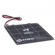
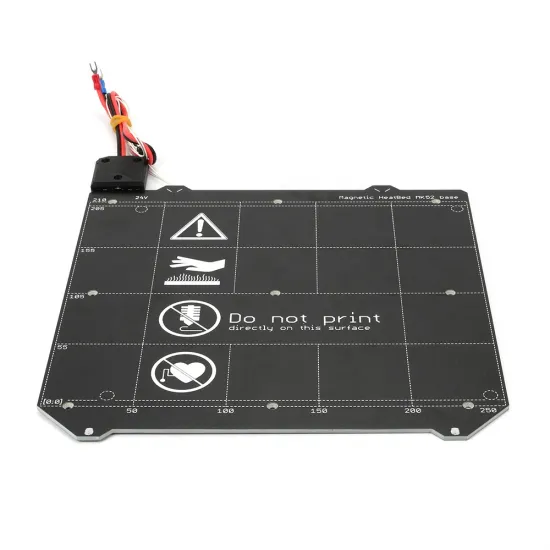
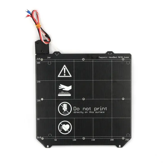
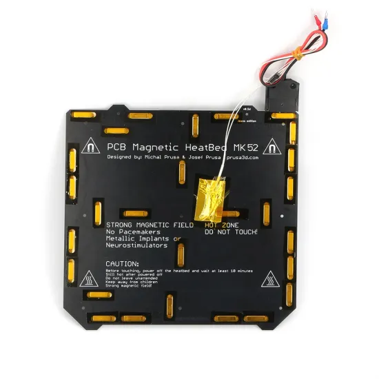
MK52-type magnetic heated bed for 24 V systems, with a declared rated power of 180 W, embedded magnets and nine mounting points. It is designed to work with a removable flexible spring-steel sheet, making it easier to change the build surface and release printed parts after cooling.
Its geometry is based on the MK52 heated beds used on Prusa i3 MK3-style printers and several derivative designs. This is a compatible or alternative product and not an Original Prusa heated bed.
Main features
- Rated voltage: 24 V DC.
- Rated power: 180 W.
- Calculated nominal current: approximately 7.5 A at 24 V.
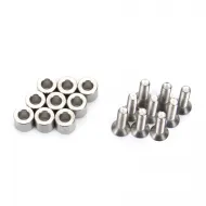
- Mounting: nine countersunk mounting holes.
- Magnetic system: magnets embedded in the rear face.
- Sensor: installed and wired thermistor.
- Power wiring: pre-installed.
- Printed grid and positioning references.
- Designed for use with an MK52-format flexible steel sheet.
Reference dimensions
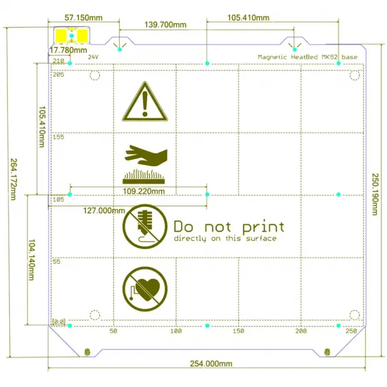
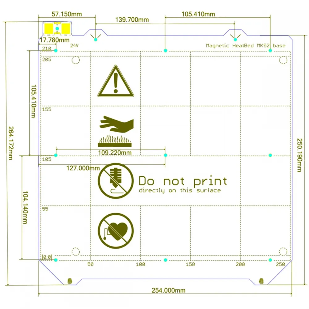
- Indicated maximum width: 254 mm.
- Main body height: approximately 250.19 mm.
- Maximum dimension including protrusions: approximately 264.17 mm.
- Printed reference area: approximately 250 × 210 mm.
These dimensions should be used to check the installation and do not automatically guarantee compatibility with a particular printer.
Required flexible sheet
The heated bed itself is not the finished surface on which printing should take place. It must be used with a flexible steel sheet compatible with MK52 geometry. The printed warning on the heated bed also states that users should not print directly on its surface.
The flexible sheet is sold separately. To retain the geometry and alignment features of this format, consider the PEI-coated flexible steel sheet for MK52 heated beds.
Compatibility
This product may suit printers and conversions based on a 24 V MK52-type heated bed, including some machines inspired by the Prusa i3 MK3 architecture. However, the MK52 designation alone does not guarantee a direct replacement.
Before purchasing or installing, compare:
- The external dimensions and available space inside the printer.
- The exact position of all nine mounting holes.
- The Y-carriage design and mounting spacers.
- The cable outlet and required cable travel.
- The 24 V electrical requirement.
- The ability of the power supply and electronics to control an approximately 180 W load.
- The thermistor connector and electrical curve.
- The flexible sheet geometry and alignment points.
- The available Z height after fitting the bed and sheet.
Interchangeability with every MK52 revision, Original Prusa MK3, MK3S, MK3S+ or derivative printer cannot be guaranteed without carrying out these checks.
Electrical connection
A nominal power of 180 W at 24 V corresponds to a theoretical current of approximately 7.5 A. The power supply, MOSFET output, terminals, connectors and cable cross-section must be rated for the actual current with an appropriate safety margin.
Before connection, measure the bed resistance, check for unexpected continuity and inspect the solder joints. If the controller’s heated-bed output cannot safely handle the load, a correctly rated and installed external MOSFET stage will be required.
Thermistor and firmware configuration
A thermistor is fitted, but the available documentation does not establish its exact electrical curve. The firmware sensor selection must match the thermistor actually installed.
- Marlin: set
TEMP_SENSOR_BEDto the verified sensor table. - Klipper: configure the correct
sensor_typeunder[heater_bed]. - RepRapFirmware: enter the electrical parameters corresponding to the actual thermistor.
Do not automatically assume a generic 100 kΩ sensor table. Before heating, confirm that the displayed temperature is consistent with room temperature. After installation, perform the thermal or PID calibration supported by the firmware and verify that thermal-runaway protection operates correctly.
Installation and calibration
- Fit strain relief so that bed movement does not fatigue the wires or solder joints.
- Make sure the mounting screws do not distort the PCB.
- Check that no metal component can cause an electrical short circuit.
- Recalibrate bed levelling, Z offset and the first layer after installation.
- Repeat first-layer calibration whenever a sheet with a different thickness is fitted.
Safety
- The heated bed and flexible sheet remain hot after power is switched off.
- Do not remove or bend the flexible sheet until the print and surface have cooled sufficiently.
- Do not exceed the operating temperatures intended for the bed, magnets and selected build surface.
- Keep the assembly away from objects that may be affected by strong magnetic fields.
- Users with pacemakers or other magnetically sensitive medical implants should take additional precautions.
Minor superficial marks caused by manufacturing, soldering or handling may be present and do not necessarily affect operation.