

- Stock: Out of Stock
- Model: FC óptico Compacto
Model:

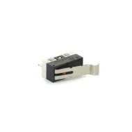
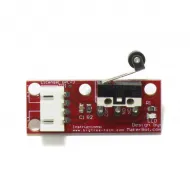
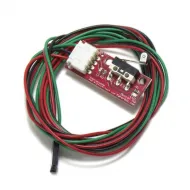
Mechanical 70cm cable

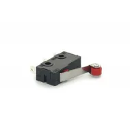
Mechanical with wheel 70cm cable

Mechanical with wheel 1m cable

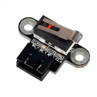
Mini Mechanic XH2.54 Horizontal

Mini Mechanic XH2.54 Vertical

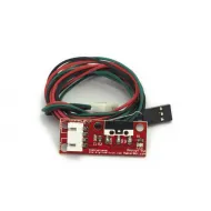
Optical 50cm cable

Compact Optical 1m cable

Mechanical KW11

Mechanical KW12-3

Mechanical D2F-5L - Omron
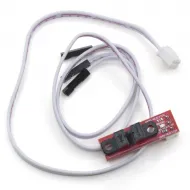
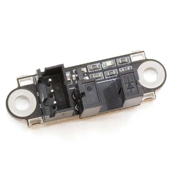
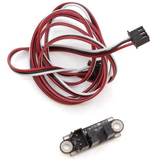
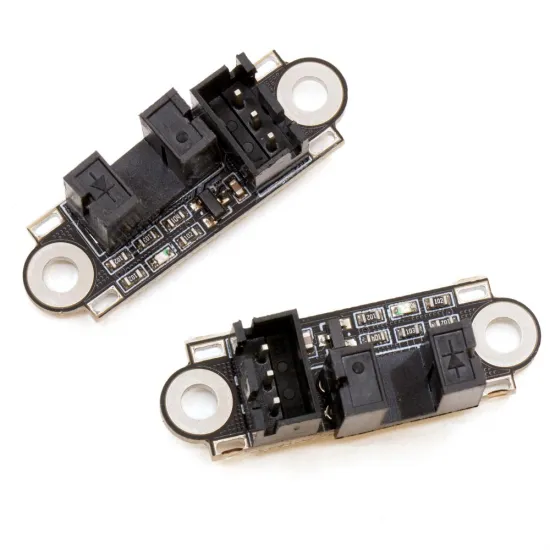
Compact optical endstop for 3D printers, CNC machines and automation projects. It detects a flag entering its slot by interrupting an infrared beam, with no mechanical contact between the moving part and the sensor.
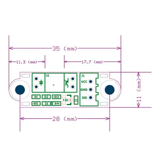
Its approximately 35 × 11 mm board is suitable for confined spaces and includes a three-conductor, 1 m cable. This is a powered sensor: VCC, GND and SIG must all be connected correctly.
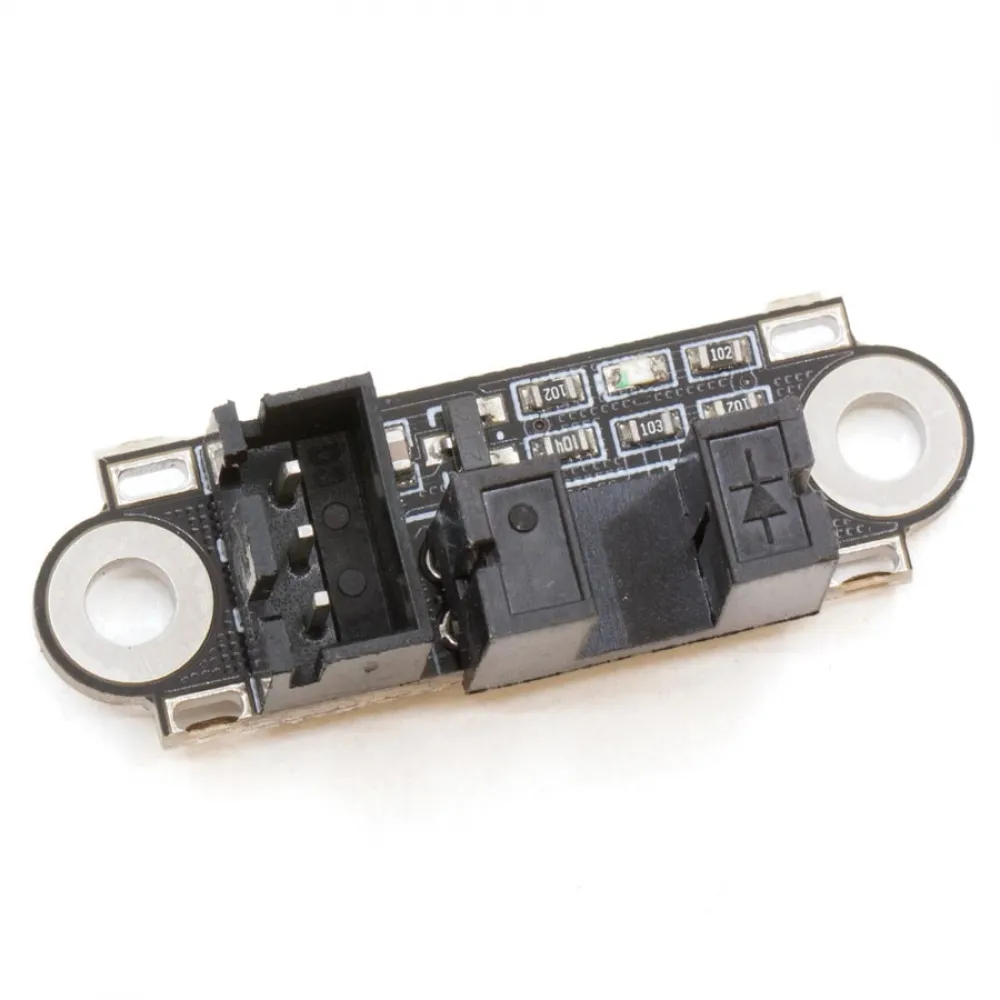
Features and dimensions
| Property | Value |
|---|---|
| Detection type | Slotted infrared optical barrier |
| Declared supply voltage | 2.7-5 V DC |
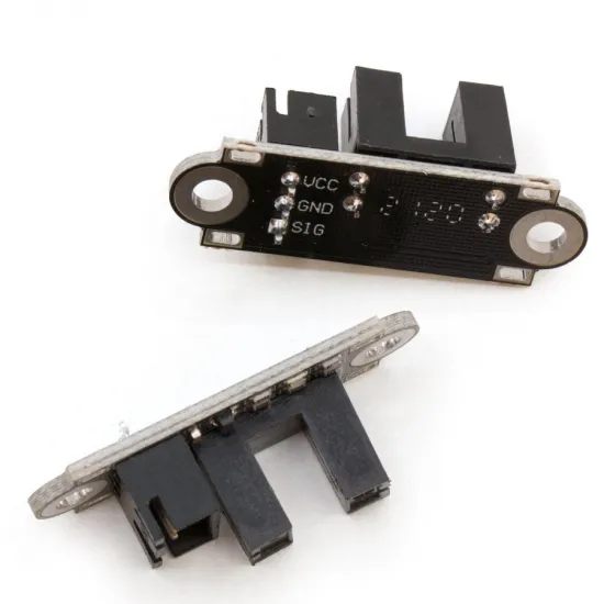
| Connections | VCC, GND and SIG, marked on the board |
| Connector | 3 positions, nominal 2.54 mm pitch |
| Cable length | Approximately 1 m |
| Board dimensions | Approximately 35 × 11 mm |
| Mounting-hole centre distance | 28 mm |
| Indicator | Status LED |
| Contents | 1 module with cable |
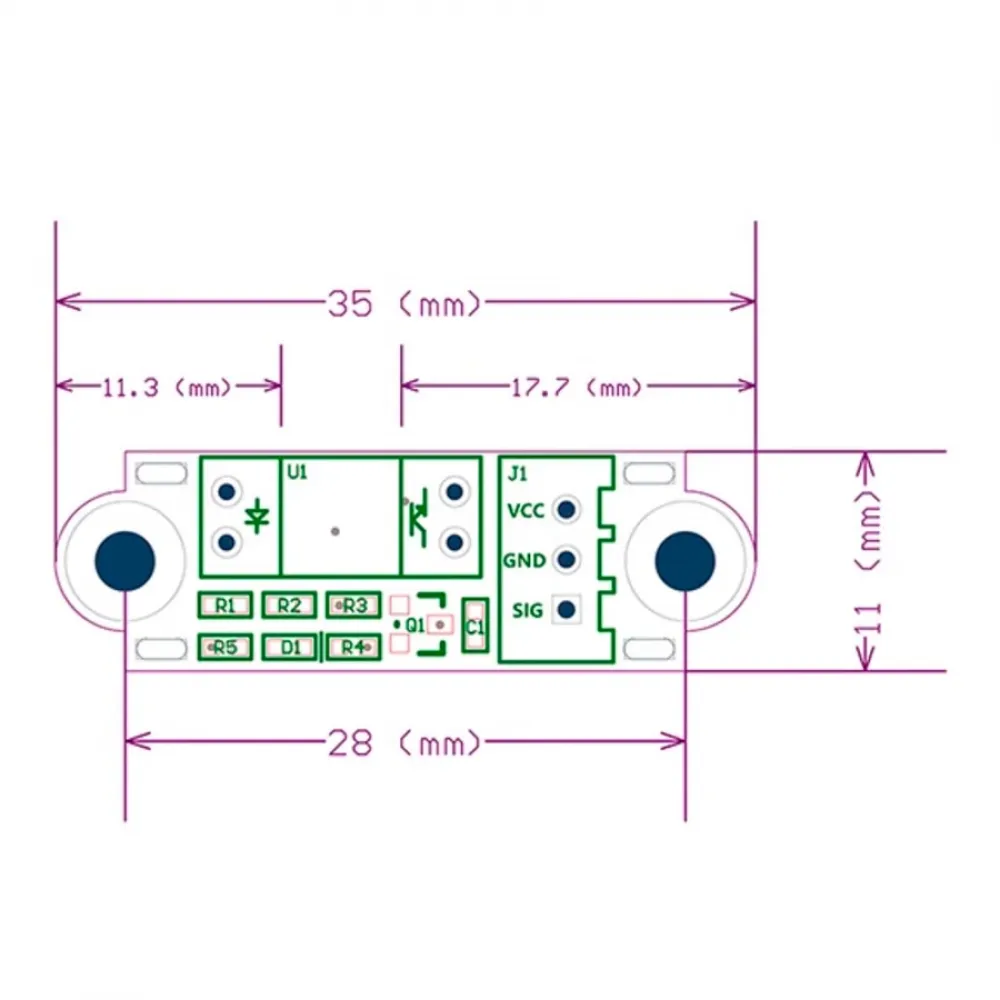
Operation and flag selection
The expected behaviour for this module family is a low signal with a clear beam and a high signal when an opaque flag interrupts the slot. As this is a generic module, verify the actual state after installation before moving the machine.
The flag must enter far enough to fully interrupt the beam without striking the housing. Use an opaque, rigid part: translucent or partly infrared-transparent materials, a very slow or partial interruption, dirt and mounting play may produce an intermediate or unstable reading.
Safe connection
Both the supply voltage and the controller's permitted logic level must be compatible. This module family's high output is referenced to VCC: when powered at 5 V, SIG may approach 5 V. With a 3.3 V controller, power it at 3.3 V or explicitly confirm that the selected input tolerates a 5 V signal. Never connect it directly to 12 or 24 V.
- Work with the machine off and disconnected.
- Locate supply, ground and signal in the controller documentation; do not assume connector order.
- Check cable continuity to identify which position reaches each marked sensor pin.
- Connect VCC to a compatible logic supply, GND to ground and SIG to an endstop input.
- Power up without commanding movement and verify that the state changes with an opaque flag.
- Only after a correct reading, test homing slowly with immediate access to emergency stop.
Marlin, Klipper and RepRapFirmware setup
Marlin
Enable the MIN or MAX connector used by the installation. For the expected logic, current releases use a HIGH hit state, such as X_MIN_ENDSTOP_HIT_STATE HIGH; older releases use the equivalent inversion option under a different name. Run M119 with the slot clear and blocked: the axis must read open when it may move and TRIGGERED when the flag is inserted. If it is reversed, correct the configuration before running G28.
Klipper
Assign the physical controller input under endstop_pin. The ! prefix reverses polarity and ^ enables a pull-up, but neither should be added automatically: they depend on the controller and measured behaviour. Use QUERY_ENDSTOPS with the beam clear and blocked until it respectively reports open and TRIGGERED; do not home before this check.
RepRapFirmware
In RepRapFirmware 3, M574 assigns the end, type and input. For an active-high input, a structure such as M574 X1 S1 P"ioN.in" may be used, replacing the axis, end and pin with the actual values. If the measured state is reversed, current documentation permits prefixing the pin name with !. Always verify the state before homing.
Compatibility and alternatives
It can be used in 3D printers, small CNC machines and automation systems with a compatible logic supply, suitable digital input and room for its geometry. Compatibility with a specific machine also depends on the bracket, flag travel, homing direction, pinout and firmware; it is not necessarily a direct replacement for every three-pin endstop.
For another geometry, consider the optical endstop with 50 cm cable or the vertical mini mechanical endstop, checking mounting, travel and connection in each case.
This product is for you if
- You need contactless detection in a confined space.
- You can design or adapt an opaque flag and a bracket with 28 mm mounting centres.
- You will verify voltage, pinout and logic before homing.
This product is not for you if
- You need a passive, two-wire switch.
- Your controller does not provide a compatible logic supply and input.
- You cannot protect the slot from impacts, dirt or a translucent flag.