Menu
Your Cart

IRF520 MOSFET module 0-24 V for PWM control of DC loads

IRF520 MOSFET module 0-24 V for PWM control of DC loads
Out of Stock
IRF520 MOSFET module 0-24 V for PWM control of DC loads
1.75€
Ex Tax: 1.45€
  • Stock: Out of Stock
  • Model: mosfet-module

Model:

1A

1A

25A

25A

30A

30A

30A Fysetc

30A Fysetc

Product out of stock
This product is out of stock, we will try to replenish it as soon as possible. You can request a notice by clicking on the green button (except discontinued products).

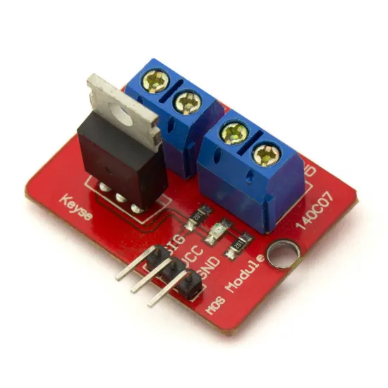
This IRF520 MOSFET module can control DC loads using a signal from an Arduino, ESP32, Raspberry Pi, controller board or other microcontroller. It can be used to switch or regulate devices such as fans, LED lighting, small pumps and other low-voltage accessories using PWM.

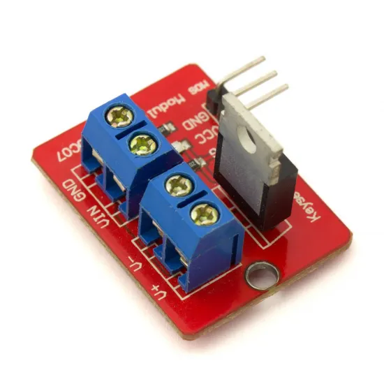
The module simplifies MOSFET wiring and allows the load to use a separate power supply from the control signal. However, it does not provide galvanic isolation. The control and power grounds must be connected according to the markings on the board.

Main features

  • N-channel MOSFET: IRF520.
  • Specified module load voltage: 0-24 V DC.
  • Module control signal: 3.3 or 5 V.
  • Suitable for digital and PWM control signals.
  • Approximate board dimensions: 33 × 25 mm.
  • Signal pins and screw terminals for the load.
  • Application: control of direct-current loads.

Important: the IRF520 is not a logic-level MOSFET

Although the module can receive a 3.3 or 5 V signal, the IRF520 may not turn on completely at these gate voltages. The component datasheet specifies its on-state resistance with a gate voltage of 10 V.

The gate threshold voltage, approximately 2 to 4 V according to the manufacturer, only indicates when the MOSFET starts to conduct a very small current. It does not mean that the transistor can control its rated current from a 3.3 V signal.

  • A 5 V signal can be used with moderate loads while monitoring temperature.
  • Conduction may be even less efficient with a 3.3 V signal.
  • Higher current may produce greater voltage drop and MOSFET heating.
  • Actual capability depends on control voltage, current, PWM, airflow, ambient temperature and cooling.

Current and thermal dissipation

This type of module is commonly advertised for currents of up to 5 A, but this figure should not be interpreted as a guaranteed continuous current in every configuration. The transistor maximum ratings are obtained under test and cooling conditions that do not necessarily represent operation on this board.

For loads close to or above 1 A, check the temperature during an extended test and consider additional cooling. If the MOSFET becomes excessively hot, reduce the current or use a more suitable power module.

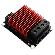
This module is not recommended for heated beds, high-power heater cartridges or other demanding loads. These applications require a purpose-built module with suitable terminals, PCB tracks and cooling, such as the BigTreeTech heated-bed MOSFET module with heatsink or the Fysetc MOSFET module with heatsink. Always check the actual load voltage and current.

Suggested applications

  • DC fans.
  • Low-voltage LED strips and modules.
  • Small DC pumps or motors.
  • Moderate-current solenoids and valves.
  • Accessories controlled through a PWM output.
  • Electronic prototypes using Arduino and other development boards.

For inductive loads such as motors, pumps, relays or solenoids, verify that suitable protection against reverse voltage is present. If neither the module nor the load includes an appropriate flyback diode, one must be added externally.

Controller-board compatibility

The module can be controlled by boards using 5 V signals, including many Arduino models, and by 3.3 V boards such as the ESP32 or certain Raspberry Pi models. Signal compatibility does not, however, guarantee the same load-current capability in every case.

With a 3.3 V signal, the load should be particularly limited and MOSFET temperature carefully checked. For controlling high currents from a 3.3 V output, a module using a logic-level MOSFET or a dedicated gate driver is preferable.

Connection precautions

  • Use only with direct current and observe the polarity marked on the board.
  • Do not connect AC loads or mains voltage directly.
  • Power the load from a supply suitable for its voltage and current.
  • Do not power the load from the microcontroller's 5 or 3.3 V pin.
  • Use cables and connectors rated for the required current.
  • Install a suitable fuse when the power supply can deliver a high fault current.
  • Make all connections with the power disconnected.
  • Check MOSFET and terminal temperature during the initial tests.

Package contents: 1 IRF520 MOSFET module.

Write a review

Note: HTML is not translated!
Bad Good
Captcha