

- Stock: Out of Stock
- Model: 23hs5628
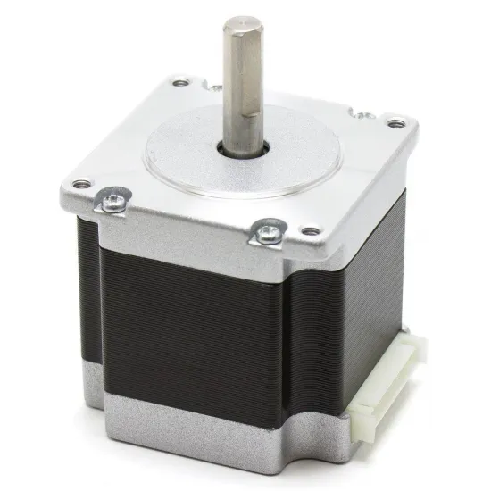
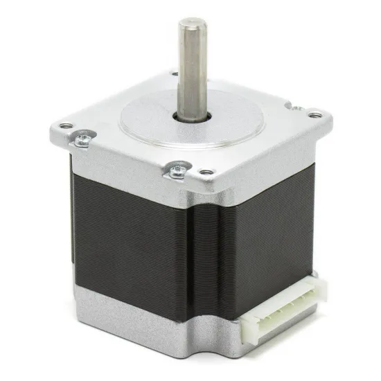
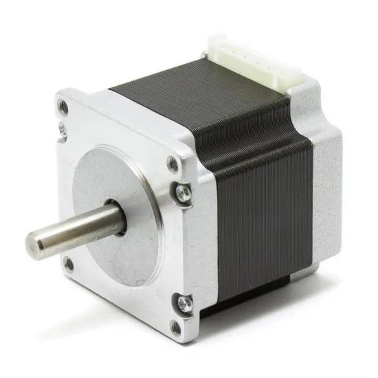
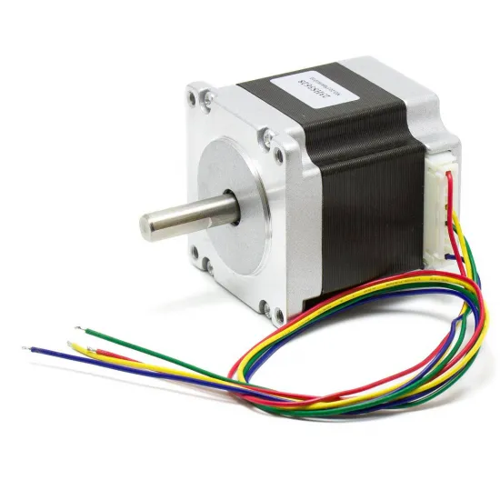
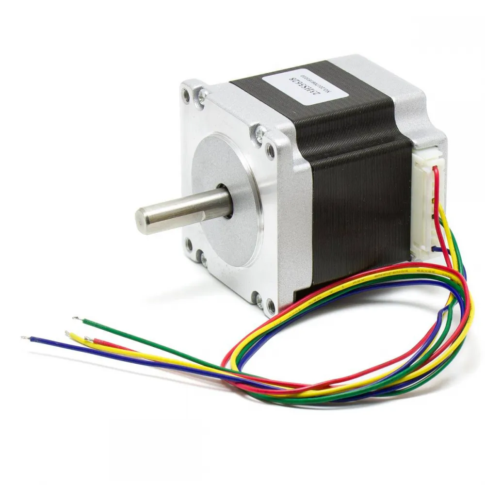
NEMA 23 23HS5628 bipolar stepper motor for CNC machines, automation, positioning systems and mechanisms that need more torque than a conventional NEMA 17 motor. Its 56 mm body provides 1.26 N·m holding torque, while the 8 mm D shaft improves the grip of correctly sized pulleys, couplings and gears.
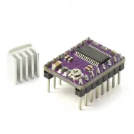
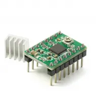
This is a 1.8°, 200-full-step-per-revolution motor rated at 2.8 A per phase. Reaching its available torque requires a bipolar driver with adequate electrical and thermal capability; it should not be paired automatically with a small StepStick module merely because both use STEP/DIR signals.
Technical specifications
| Feature | Value |
|---|---|
| Model | 23HS5628-8MM |
| Type | 2-phase, 4-wire bipolar hybrid stepper motor |
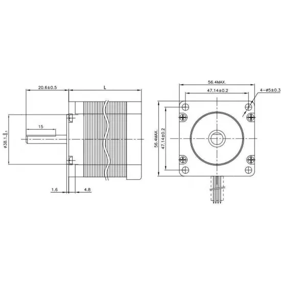
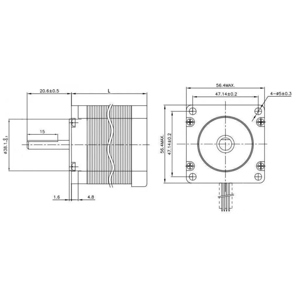
| Frame | NEMA 23, 56.4 mm maximum face size |
| Step angle | 1.8°; 200 full steps per revolution |
| Rated current | 2.8 A per phase |
| Phase resistance | 0.9 Ω per phase |
| Phase inductance | 2.5 mH per phase |
| Holding torque | 126 N·cm = 1.26 N·m ≈ 12.8 kgf·cm |
| Rotor inertia | 300 g·cm² |
| Body | 56 mm long |
| Shaft | Ø8 mm D shaft; 20.6 ± 0.5 mm projection; 15 mm flat |
| Mounting | 4 × Ø5 ± 0.3 mm holes; 47.14 ± 0.2 mm centres |
| Pilot | Nominal Ø38.1 mm |
| Weight | Approximately 700 g |
| Cable | 4 wires, approximately 30 cm |
Applications and motor selection
The NEMA 23 frame and 1.26 N·m holding torque suit CNC axes, leadscrews, positioning tables, rotary mechanisms and automation when load, speed and acceleration calculations fall within its operating capability. Its 700 g mass must also be considered: it is generally better suited to a fixed base or axis than to a lightweight, high-acceleration moving carriage.
Holding torque is not the torque available throughout every movement. Usable torque falls as speed increases and depends on system voltage, driver, current, microstepping, acceleration, transmission and resonances. Design with margin and test progressively under the real load.
Mechanical compatibility: NEMA 23 is not enough
Check all of the following before replacing a motor or designing its bracket:
- 47.14 mm mounting pattern, four-hole diameter and Ø38.1 mm pilot.
- Clearance for a 56.4 mm face, 56 mm body and approximately 700 g mass.
- 8 mm D shaft, usable projection and the position of pulley, coupling or gear set screws.
- Required torque and speed after transmission ratio is considered.
- Current, inductance, driver, power supply and cooling.
- Coil pairs, cable arrangement and controller STEP/DIR inputs.
The 8-to-8 mm rigid coupling can only be used when both shafts are truly 8 mm, properly aligned and a rigid connection is appropriate. A rigid coupling does not compensate for misalignment in the way a flexible coupling can.
Driver selection and current setting
2.8 A per phase is the motor rating, not a universal setting to copy into every driver. Check whether the controller specifies RMS or peak current, its real continuous current capability, permissible voltage, heat dissipation and cooling requirements.
Approaching rated torque requires an external or integrated bipolar driver with sufficient margin for 2.8 A per phase. Small plug-in modules commonly used in 3D printers may accept compatible control signals, but many cannot sustain 2.8 A continuously with comfortable thermal margin. The motor may be operated at a lower current where necessary, but it will develop less torque.
At 2.8 A and 0.9 Ω, the nominal resistive voltage drop is about 2.52 V per winding. The motor should therefore not be labelled simply as a “12 V” or “24 V” motor. A chopper driver regulates current and permits a higher supply voltage within its limits, helping current rise against winding inductance as speed increases.
External drivers with DIP switches normally set current and microstepping on the driver itself. Verify whether their table specifies RMS or peak current, and isolate all power before changing switches or wiring.
Safe two-coil wiring
- Disconnect the power supply and allow the electronics to discharge.
- Use a multimeter to find the first pair of wires showing continuity or low resistance.
- The two remaining wires form the second coil; verify them as well.
- Connect one pair to A+/A− and the other to B+/B− according to the driver manual.
- Test direction with a short movement. To reverse it, swap both wires of one coil or use firmware direction inversion.
Wire colours are not a universal standard, and a physically matching connector may use a different pin order. Never connect or disconnect the motor while its driver is powered.
Steps per millimetre and transmission
At 1.8° per step, the motor performs 200 full steps per revolution. Axis calibration follows the real mechanism:
steps/mm = (200 × microsteps × reduction ratio) / travel per output revolution
- Direct leadscrew: travel per revolution is its lead in mm/revolution.
- Belt: travel is belt pitch multiplied by pulley tooth count.
- Gear reducer: multiply by the number of motor turns required for one output turn.
- Rotary axis: configure steps per degree or another angular unit as supported by the controller.
Marlin, Klipper and RepRapFirmware setup
- Marlin: configure actual microstepping at the driver and set steps per unit with
M92or in firmware. UseM500only when EEPROM is enabled and the setting should be stored. - Klipper: use
full_steps_per_rotation: 200and setrotation_distanceto actual travel per revolution; addgear_ratiowhere a reduction is used. With an external STEP/DIR driver, current is usually set in hardware rather than in a TMC section. - RepRapFirmware: use
M350for microstepping andM92for steps per unit.M906only controls current on compatible firmware-managed drivers and does not replace switches on an external driver.
Microstepping makes motion smoother and increases command resolution, but it does not guarantee that each microstep produces equal physical accuracy. Measure real travel, inspect backlash and correct the final calibration on the assembled mechanism.
Recommended commissioning procedure
- Mount the motor on a rigid structure and ensure the front pilot seats without interference.
- Align the shaft and avoid unintended radial or axial loads.
- Set current, microstepping and supply voltage according to the driver manual.
- Begin at low speed and acceleration without a dangerous tool or load.
- Check direction, travelled distance, noise, resonance and temperature.
- Increase demand gradually and stop if missed steps or abnormal heating occur.
This is an open-loop system: the motor alone does not report missed steps to the controller. Correct alignment, sensible acceleration and a properly sized driver are essential to preserve position.
Package contents
- 1 NEMA 23 23HS5628 stepper motor with 8 mm D shaft.
- Approximately 30 cm four-wire cable.