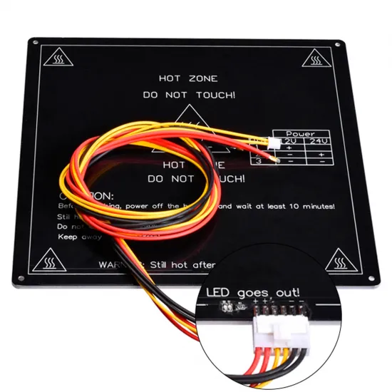


- Stock: 19
- Model: MK3-220x220-12v-C
Model:

MK2B 12V / 24V

MK3 12V / 24V

MK3 220x220 12V / 24V

MK3 220x220 12V + Wires

ALU 220x280 12V

MK3 235x235 24V

MK3 235x235 24V + Wires

ALU 329x329 24V

MK3 400x400 24V
MK3 500x500 24V
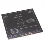
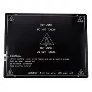
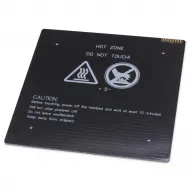
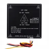
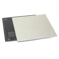
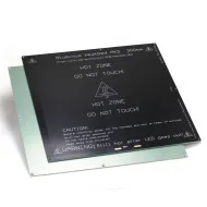
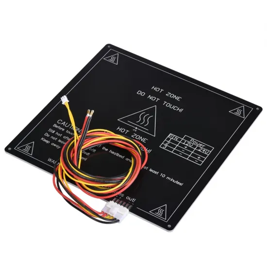
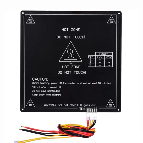
220 × 220mm MK3 ALU heated bed prepared for 12V operation at approximately 96W. It includes an approximately 90cm harness, power connection and installed thermistor, avoiding the need to solder the main wiring directly to the plate.
The 3mm aluminium core provides rigidity and distributes heat, while four countersunk holes allow mounting screw heads to sit flush.
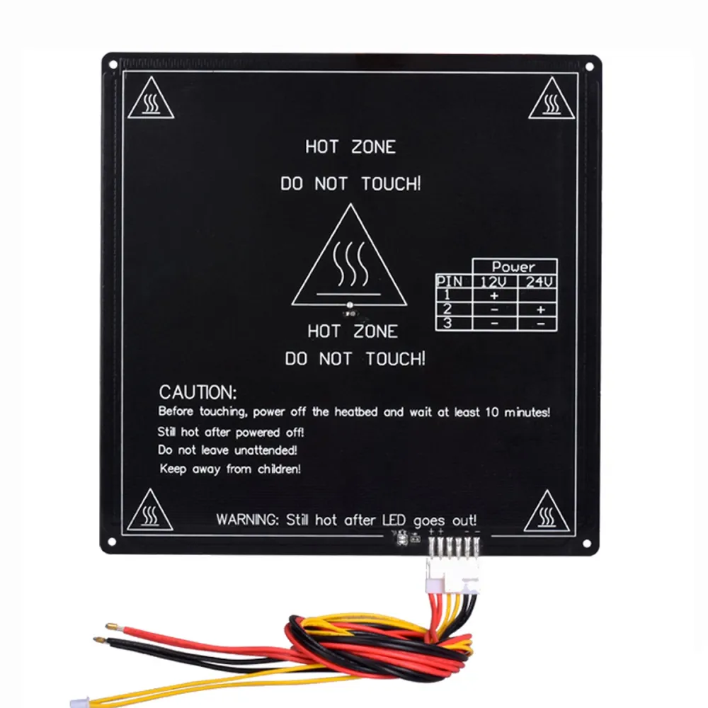
Main specifications
| Dimensions | 220 × 220 × 3mm |
|---|---|
| Supply | 12V DC |
| Declared power | Approximately 96W |
| Derived values | Approximately 8A and 1.5Ω nominal |
| Wiring | Approximately 90cm harness with connectors |
| Sensor | Installed thermistor; curve and pinout must be verified |
| Mounting | Four countersunk holes |
| Declared maximum temperature | 180°C; not a recommended setpoint |
Harness checks
Power and sensor conductors end in separate connectors. Before connecting them to the controller, trace each conductor with a continuity meter and verify polarity, pinout and connector type. Do not repin a connector based only on wire colour or a mechanically matching housing.
The cold bed should measure close to 1.5Ω after allowing for meter-lead resistance. The thermistor should show a plausible room-temperature reading and change smoothly when warmed by hand. Its curve is not identified by the photographs, so it must not be configured automatically as Beta 3950 without confirmation or measurement.
Power supply, control and safety
The bed draws approximately 8A. The supply must also power the controller, motors, hotend and fans with suitable margin. The bed output must handle 8A continuously across its MOSFET, PCB, terminals and cooling; if this is not documented, use a correctly sized 12/24V external MOSFET module.
- Disconnect power before inserting or removing connectors.
- Add strain relief so movement cannot load the contacts or sensor area.
- Monitor wires, connector, MOSFET and solder joints during the first cycles.
- Keep thermal protection enabled; a failed MOSFET can leave the bed permanently powered.
Firmware
Identify the thermistor first. If a 100K B3950 NTC is confirmed, Marlin type 11 with a 4.7kΩ pull-up, Klipper Generic 3950, or the equivalent NTC/Beta definition in RepRapFirmware may be used. Knowing only that a sensor is “100K” is not sufficient.
With the final assembly installed, PID may be retuned using M303 E-1 C8 S60 in Marlin, PID_CALIBRATE HEATER=heater_bed TARGET=60 in Klipper, or M303 H0 S60 for a bed configured as heater 0 in RepRapFirmware. Supervise the test.
Build surface and compatibility
The aluminium face can support glass or a magnetic system, but each layer adds mass and thermal inertia. The 220 × 220mm smooth/textured PEI sheet requires a compatible magnetic base; then recalibrate Z offset, first layer and PID.
Conditionally compatible with RepRap, Prusa i3 derivatives, P3Steel, 3DSteel, Anet A8 and conversions accepting a 220 × 220mm bed, four mounting points, 12V, approximately 8A and the harness exit. It is not a direct Ender-3 replacement or a replacement for other 235 × 235mm physical platforms without mechanical and electrical adaptation.
For a custom 12 or 24V installation without harness or sensor, see the dual-voltage 220 × 220mm MK3 ALU heated bed.