

- Stock: 19
- Model: Mk3-235x235-24V
Model:

MK2B 12V / 24V

MK3 12V / 24V

MK3 220x220 12V / 24V

MK3 220x220 12V + Wires

ALU 220x280 12V

MK3 235x235 24V

MK3 235x235 24V + Wires

ALU 329x329 24V

MK3 400x400 24V
MK3 500x500 24V
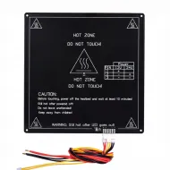
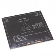
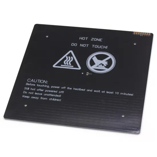
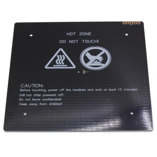
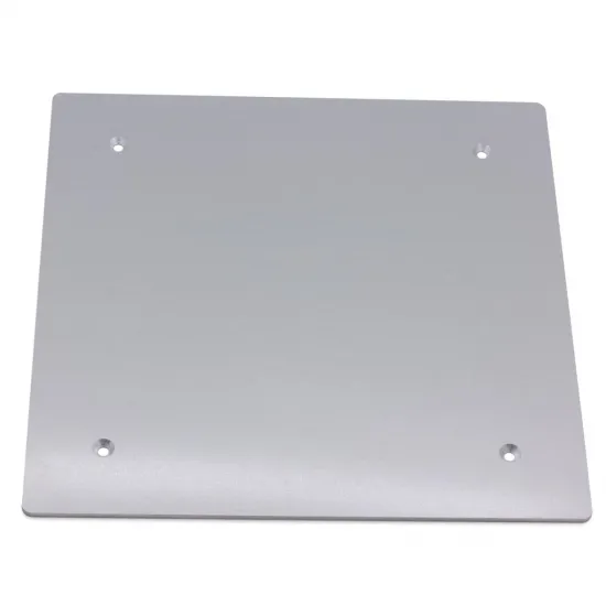
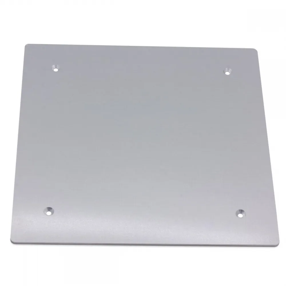
MK3 ALU 235 × 235 mm heated bed for 24 V systems, built on a 3 mm aluminium plate and rated at 240 W. Its four countersunk mounting holes allow flat-head screw heads to sit flush with the top surface.
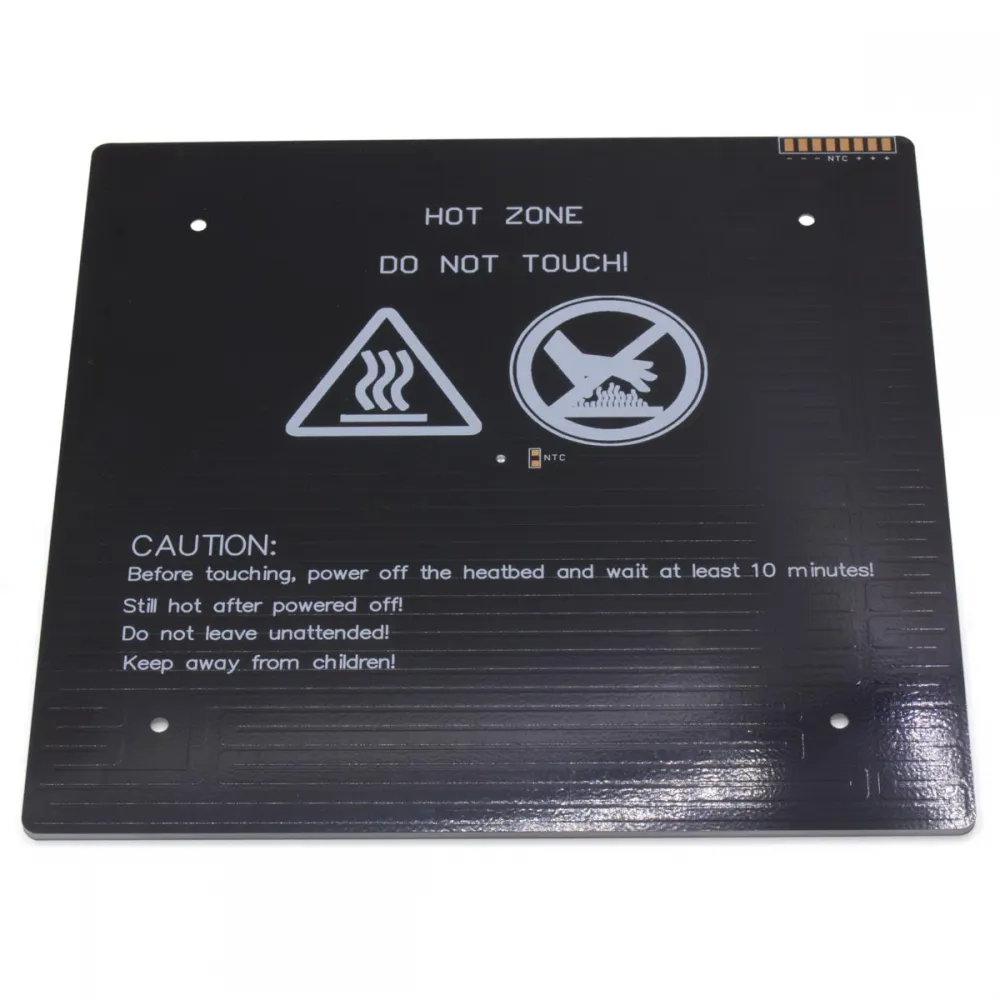
This version is supplied without wires or a fitted thermistor. It provides large connection pads and marked positions for an NTC sensor, making it suitable for builds, repairs and conversions carried out by users with electrical installation experience.
Specifications and load
| Property | Value |
|---|---|
| Nominal dimensions | 235 × 235 mm |
| Plate thickness | 3 mm |
| Supply | 24 V DC |
| Nominal power | 240 W |
| Calculated nominal current | 10 A at 24 V |
| Calculated nominal resistance | Approximately 2.4 Ω when cold |
| Mounting | 4 countersunk holes; nominal 170 mm spacing between adjacent mounting points |
| Top face | Aluminium |
| Bottom face | Black heater circuit with connection and NTC positions |
Current and resistance are calculated from the stated 24 V and 240 W; they do not replace measurement of the supplied unit. Actual resistance may vary with tolerance and temperature.
Contents and required components
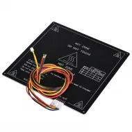
One heated bed is supplied without wiring, thermistor, power supply, power module, print surface, insulation, screws or spacers. For the same format with approximately 90 cm of wiring, choose the pre-wired 24 V MK3 ALU 235 × 235 mm version.
235 × 235 mm print surfaces
Borosilicate glass
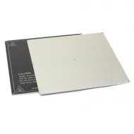
The 235 × 235 × 5 mm tempered borosilicate glass matches the bed footprint and provides a rigid removable surface. Its 5 mm thickness adds height, mass and thermal inertia; check moving-axis capacity and recalibrate Z offset, levelling and the first layer.
It may be secured with spring clips for glass and heated beds when the combined thickness and accessible edge are suitable. Keep the clips outside nozzle and probe travel, and verify underneath that they do not touch tracks or connections.
Flexible PEI sheets
This aluminium bed does not contain magnets. A compatible adhesive magnetic base is required before using a flexible sheet. The current descriptions of these 235 × 235 mm versions state that a soft magnetic base is included:
Confirm the current option contents before ordering. Fit the magnetic base only after bolting the bed down and checking flatness: its adhesive may cover the countersunk holes and make later servicing difficult. Verify its temperature rating and recalibrate the first layer whenever surface thickness changes.
Wiring for a 10 A load
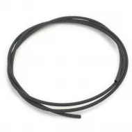
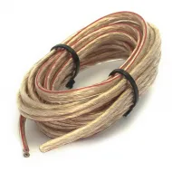
For a flexible custom connection, use red 12 AWG silicone wire and black 12 AWG silicone wire when the pads, terminals and connectors accept this size. Length, temperature, bundling, voltage drop and movement also affect circuit capacity.
- Make fully wetted solder joints without bridges.
- Add strain relief so bed movement never flexes the solder joints directly.
- Avoid generic connectors without a documented continuous-current rating above the real load.
- Use suitable ferrules or terminals in screw clamps; do not trap loose strands or tinned ends where the terminal manufacturer does not allow them.
- During the first heat cycle, verify that wires, joints, terminals and connectors do not become abnormally warm.
Thermistor and temperature control
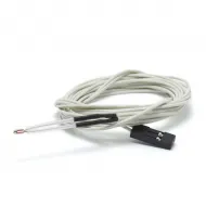
The bed has marked NTC positions, but the sensor is not included. A 100K Beta 3950 NTC with Dupont connector or a 100K Beta 3950 NTC with XH connector may be used only when mounting, connector, pinout, controller input and firmware all match.
The sensor must be firmly coupled near the thermal centre and electrically insulated. Before powering the heater, confirm a sensible room-temperature reading and check that it rises smoothly when the sensor is warmed by hand.
24 V power supply and power stage
The bed draws a nominal 10 A. A 24 V, 10 A, 240 W supply would operate at its limit with the bed alone and is not an appropriate whole-printer supply. Add the maximum demand of the bed, hotend, motors, fans, controller and accessories, then retain operating margin.
- The 24 V, 15 A, 360 W power supply may suit a dedicated bed branch or a printer whose verified total load remains within its capacity with margin.
- The 24 V, 25 A, 600 W power supply provides more capacity for higher-load systems, but is oversized for the bed alone and requires appropriate protection on each branch.
The controller's bed output must handle 10 A continuously with margin across its MOSFET, PCB, terminal and cooling. Where its rating is insufficient or undocumented, a 12/24 V external MOSFET module may be inserted after checking its true continuous rating, cooling and terminals. Do not use an AC-only solid-state relay for this 24 V DC load.
Installation and commissioning
- Verify that the carriage accepts 235 × 235 mm, the approximate 170 × 170 mm pattern, the countersinks and the cable exit.
- Bolt the bed down without bending it; screw heads must sit flush and no spacer may touch underside tracks.
- With the bed cold and disconnected, measure close to 2.4 Ω—compensating for meter-lead resistance—and verify that there is no continuity to the aluminium.
- Install the thermistor, power wiring and strain relief.
- Configure the real sensor, temperature limits and failed-heating or thermal-runaway protection in firmware.
- Perform the first heat cycle at a low target under continuous supervision and with an independent temperature reference.
- After fitting the final surface and insulation, run the thermal calibration or autotune required by the firmware.
- Recalibrate levelling, Z offset and the first layer.
Insulation and maintenance
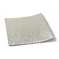
The three-layer heated-bed thermal insulation can reduce underside heat loss. Its metallised faces are conductive: they must not touch tracks, joints, sensor or terminals, and its dimensions and temperature rating must be checked before installation.
Regularly inspect solder joints, wires, strain relief, terminals and mountings. Keep thermal protection enabled and never leave the bed unattended during testing. The surface remains hot after power is removed; wait at least 10 minutes before touching it.
Conditional compatibility
Sharing a 235 × 235 mm footprint does not guarantee a direct replacement. Hole pattern and diameter, carriage, travel, cable exit, permissible mass, Z height, 24 V supply, thermistor and 10 A electrical capacity must also match. No automatic compatibility with a specific printer model is claimed without measuring its exact revision.