

- Stock: Out of Stock
- Model: 30A mosfet-module
Model:

1A

25A

30A

30A Fysetc
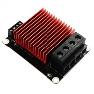
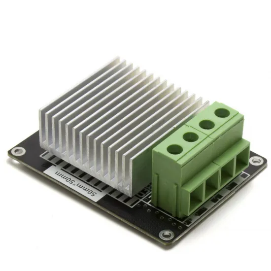
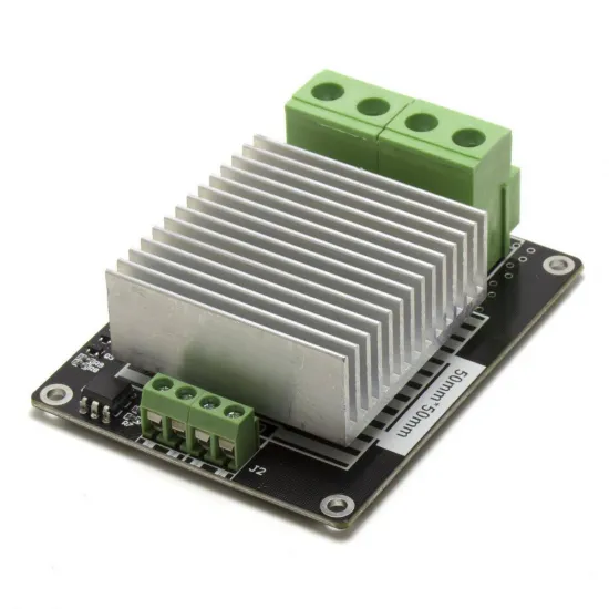
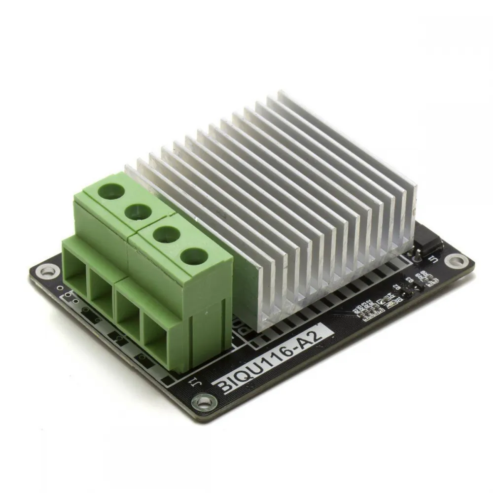
The BIQU116-A2 is an external MOSFET module used to switch a 12 or 24V DC heated bed or another resistive load from a controller board's heater output. The electronics retain temperature regulation while the module switches current supplied directly by the power supply.
Its large heatsink, separate screw terminals for power and control, and specific four-wire layout make it useful both as a replacement for another BIQU116-A2 and in a correctly sized custom installation.
Main specifications
| Type | External MOSFET stage for resistive DC loads |
|---|---|
| PCB reference | BIQU116-A2 |
| Load voltage | 12 or 24V DC; 24V maximum |
| Advertised current | Up to 30A nominal, subject to cooling and installation |
| Connections | J1 for supply and load; J2 for control signal |
| Mounting | Four PCB mounting holes |
| Contents | 1 MOSFET module |
What it does—and what it does not do
The controller's bed output provides the on/off or PWM command, but the main current flows from the power supply to the bed through the module. This reduces the load carried by the controller board's built-in MOSFET and terminal.
The module does not convert voltage, increase the power supply's capacity, or regulate temperature by itself. A correctly configured sensor, firmware and thermal protection remain essential.
BIQU116-A2 connections
When facing the connectors, the documented layout is:
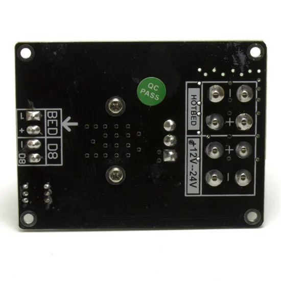
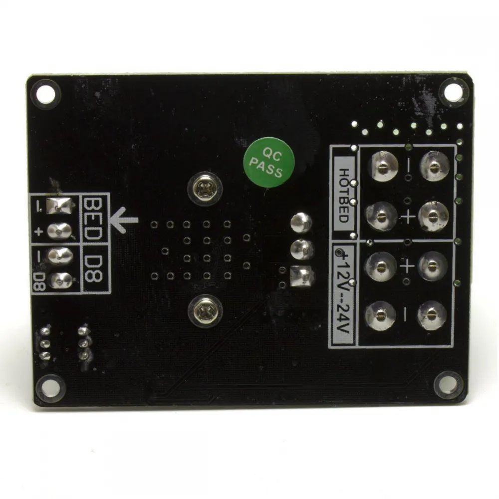
- J1: bed output −, bed output +, power-supply input + and power-supply input −.
- J2: D8, GND, bed control input + and bed control input −.
For a conventional installation, connect the 12/24V supply to the +12V-24V section, the bed to HOTBED, and the controller's heated-bed output to the BED +/− pair. Always follow the silkscreen and verify polarity with a multimeter before applying power.
The D8/GND terminals are intended for installations whose pinout and signal level match the BIQU116-A2. Do not connect an arbitrary 3.3 or 5V GPIO directly without checking the controller diagram and required signal, and do not drive both control inputs simultaneously.
Sizing the installation
The 30A figure is an advertised nominal maximum, not a continuous-current guarantee for every installation. Actual capacity is limited by the transistor, PCB, solder joints, terminals, heatsink, airflow, ambient temperature, wires and terminations.
For a resistive load, estimate current using I = P / V. A 240W bed at 24V, for example, draws approximately 10A; a 120W bed at 12V also draws about 10A. Size the supply, wiring and fuse from the actual load with suitable margin, not from the 30A product name.
It may be used with the 235 × 235mm, 24V, 240W MK3 aluminium heated bed or the pre-wired 24V version, provided the whole installation is sized for their nominal 10A load. Check voltage, power and connection separately for any other build.
Installation and safety
- Fully disconnect power before installation or retightening.
- Use correctly sized wire and suitable ferrules; do not tin stranded wire ends clamped by screw terminals.
- Mount the PCB on a non-conductive support, protect it from short circuits and provide airflow around the heatsink.
- Provide strain relief for moving bed wiring.
- Fit appropriate fuses to protect the wiring and load. An independent thermal fuse can add another safety layer when its current, temperature and installation suit the project.
- During the first cycles, monitor wires, terminals, solder joints and heatsink for heat, smell or discolouration.
- If the bed heats without a command, disconnect power immediately: a MOSFET can fail short circuit.
This module is for low-voltage direct current. It must not be connected to a mains-powered bed and does not replace an AC-rated SSR or contactor.
Firmware: Marlin, Klipper and RepRapFirmware
If the same bed output and sensor are retained, the pin and thermistor type do not change: the firmware continues to control heater_bed as before. The external module is not configured as another device.
- Marlin: if bed PID tuning needs to be repeated, use
M303 E-1 C8 S60and apply/save the result according to the firmware version and EEPROM configuration. - Klipper: use
PID_CALIBRATE HEATER=heater_bed TARGET=60, review the result and then runSAVE_CONFIG. - RepRapFirmware: for a bed configured as heater 0, use
M303 H0 S60; review it withM307 H0and transfer the result toconfig.g.
60°C is only a common example. Supervise any autotune and verify the sensor and thermal protection first.
Compatibility
It is a direct replacement only when the machine already uses a BIQU116-A2 with the same wiring. In RepRap, Prusa i3-derived, Anet, Creality or other modified machines, compatibility is conditional: DC voltage, current, control output, polarity, available space, mounting and wiring capacity must all match. The printer name alone is not sufficient.
For an alternative currently available with a dedicated control input, see the V1.3 25A external MOSFET module. The FYSETC MOSFET module for 12/24V loads is also available.