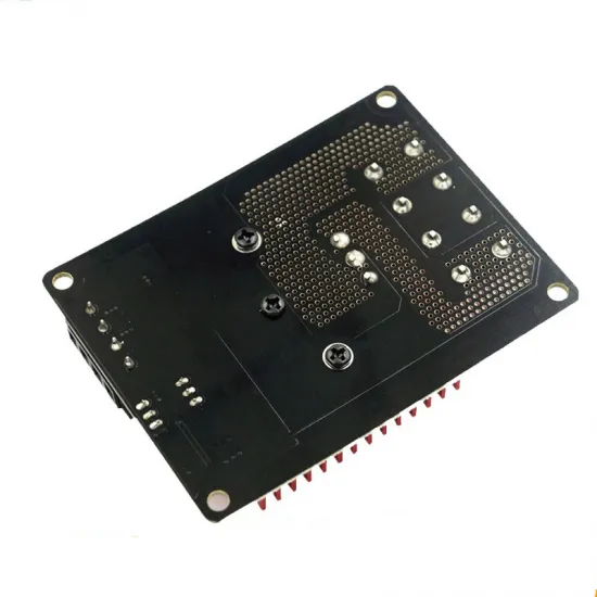


- Stock: 11
- Model: Mosfet-30A-Fysetc

Model:

1A

25A

30A

30A Fysetc
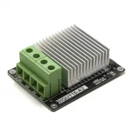
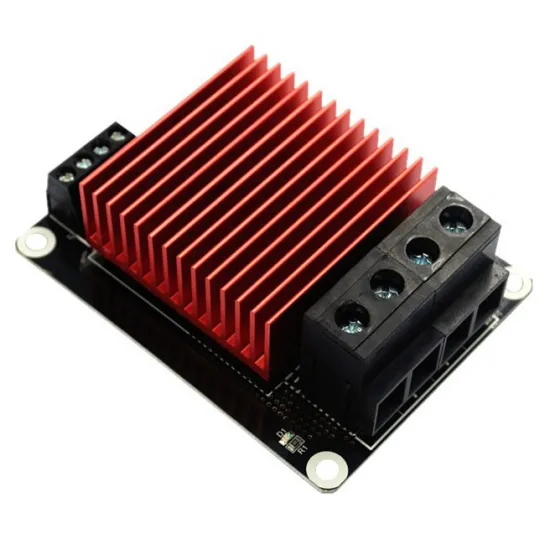
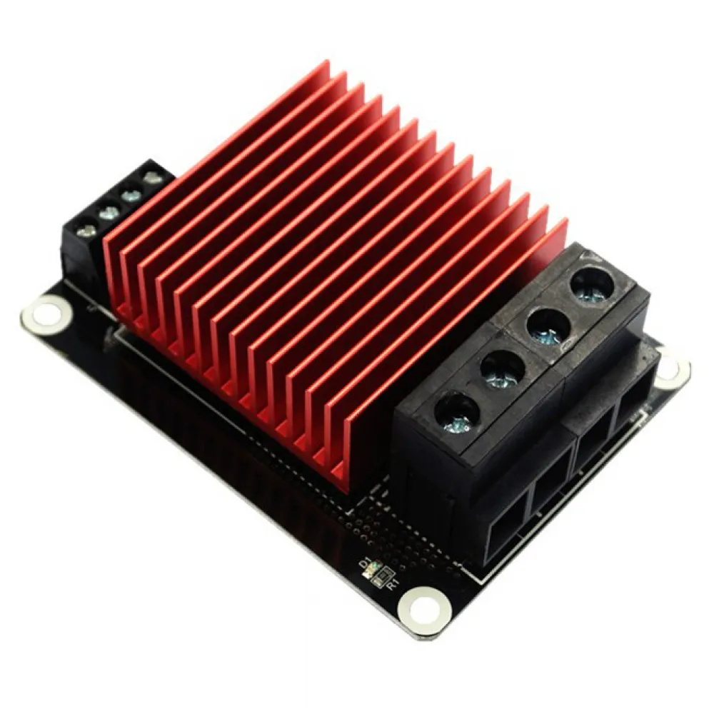
External MOSFET power stage with a large heatsink for controlling heated beds, heaters and other resistive DC loads in 3D printers and similar machines.
The module allows the controller board to continue regulating temperature while the main heated-bed current is supplied directly by the power supply. This reduces the load passing through the controller board connector and onboard power stage.
Main features
- Compatible with 12 and 24 V DC power systems.
- Maximum supply and load voltage: 24 V DC.
- Digital control signal input from 5 to 24 V DC.
- Can be controlled from the heated-bed output of a compatible controller board.
- Advertised nominal maximum current: up to 30 A.
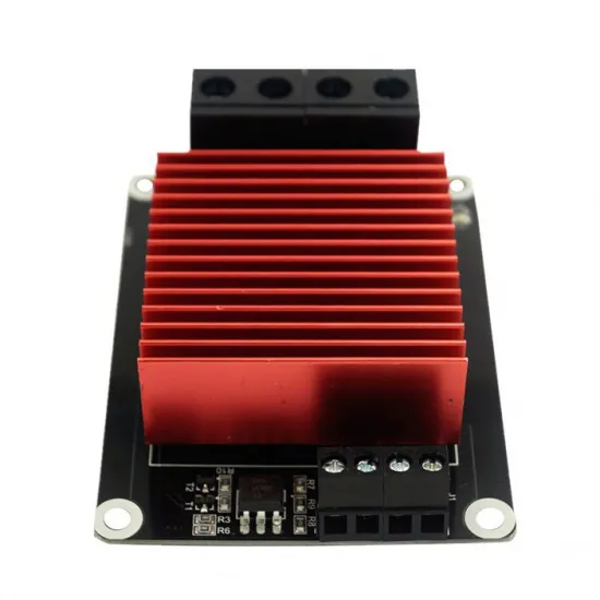
- Large aluminium heatsink for improved heat dissipation.
- Operating status LED.
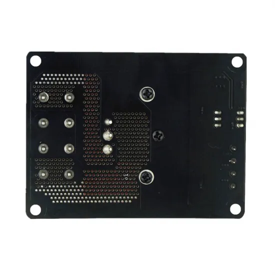
- Four module mounting holes.
| Brand | FYSETC |
|---|---|
| Load supply | 12 or 24 V DC, 24 V maximum |
| Control signal | 5-24 V DC |
| Current | Up to 30 A nominal maximum; continuous capability depends on wiring, terminals, airflow and temperature |
| Approximate dimensions | 87 × 65 × 30 mm |
| Contents | 1 FYSETC MOSFET module |
How it works
The printer controller board retains control of the heated bed and reads the temperature sensor. The MOSFET module acts only as an external switching stage, taking power from the supply and delivering it to the bed when commanded by the controller.
It is not a voltage regulator, DC-DC converter or independent temperature controller. It does not increase the rated power of the heated bed by itself.
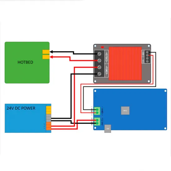
Wiring diagram
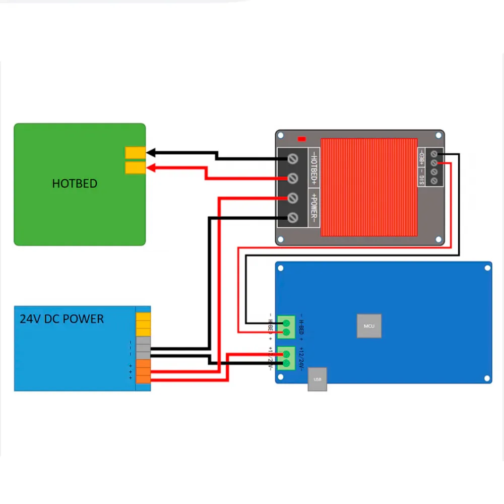
- Completely disconnect the printer from its power supply.
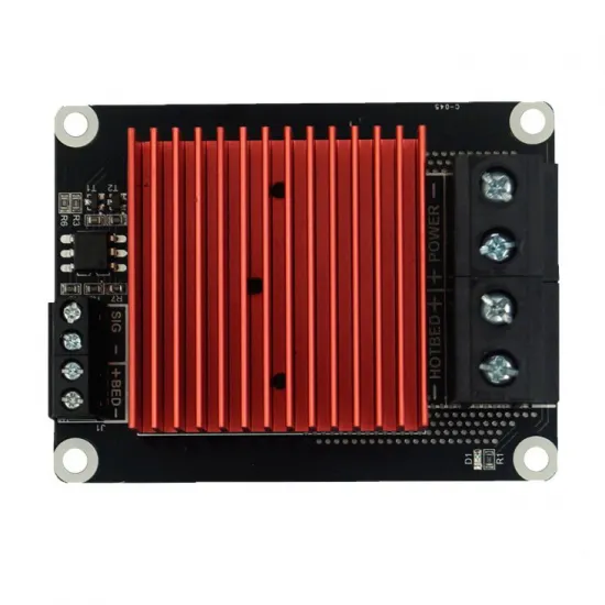
- Connect the 12 or 24 V DC power supply to the terminals marked POWER.
- Connect the heated bed or resistive load to the HOTBED terminals.
- Connect the controller board heated-bed output to the BED control input, following the module markings.
- Carefully check polarity, terminal tightness and insulation before restoring power.
The power supply, heated bed and other components must operate at compatible voltages. The module does not convert a 12 V supply into 24 V and does not allow a 12 V bed to be powered directly from 24 V.
Controller board compatibility
It can be used with RAMPS 1.4, compatible MKS boards and other controllers whose heated-bed output or control signal is within the 5 to 24 V DC range.
Compatibility must be checked electrically. Using Marlin, Klipper or RepRapFirmware alone does not guarantee compatibility; the output voltage, polarity and switching behaviour must also be verified.
Current, wiring and cooling
The 30 A figure is an advertised nominal maximum, not a universal continuous operating recommendation. Actual capacity is limited by the transistor, PCB, terminals, solder joints, heatsink, airflow, wiring and fuse.
The approximate current of a resistive load can be calculated by dividing its power by its voltage:
- A 240 W bed at 24 V draws approximately 10 A.
- A 240 W bed at 12 V draws approximately 20 A.
The same power therefore requires twice as much current at 12 V. Operation close to the nominal maximum is not recommended without thermal testing, suitable wiring and correctly sized protection.
Safe installation recommendations
- Use wiring with sufficient cross-section for the actual load current.
- Use suitable ferrules or terminals in the screw connectors. Do not tin flexible wire ends intended for screw terminals.
- Install a fuse sized to protect both the wiring and the load.
- Mount the module on a non-conductive support and leave clearance around the heatsink.
- Avoid mechanical stress on the terminals and provide strain relief for moving heated-bed wiring.
- Check the temperature of the module, cables and connectors during the first heating cycles.
- Regularly inspect for discolouration, smell, loose connections or signs of overheating.
- Only retighten connections with all power completely disconnected.
- Keep firmware thermal-runaway protection enabled.
- An independent thermal fuse is recommended for high-power heated beds.
A MOSFET can fail short-circuit and leave the heated bed permanently powered. If the bed starts heating without a command, immediately disconnect the power and inspect the module and wiring.
Marlin, Klipper and RepRapFirmware configuration
It is normally unnecessary to change the heated-bed pin, sensor type or basic firmware configuration. The controller continues to operate its normal bed output and the module works as an external power stage.
If the heating response changes noticeably after installation, the thermal tuning can be repeated:
- Marlin: for a PID-controlled bed, use
M303 E-1 C8 S60 U1and save the result withM500when EEPROM support is enabled. - Klipper: run
PID_CALIBRATE HEATER=heater_bed TARGET=60, followed bySAVE_CONFIG. - RepRapFirmware: if the bed is configured as heater 0, use
M303 H0 S60, inspect the result withM307 H0and add the resulting parameters toconfig.g.
Before autotuning, verify that the sensor reports correctly, the bed switches off when commanded and thermal protection is active. Never leave the machine unattended during this procedure.
Important
For compatible DC loads only. Do not use it with a heated bed connected directly to mains voltage: this module is not an AC solid-state relay.
Power cables, ferrules, fuse, fuse holder, mounting hardware and thermal fuse are not included.