

- Stock: Out of Stock
- Model: UNO R3-au16
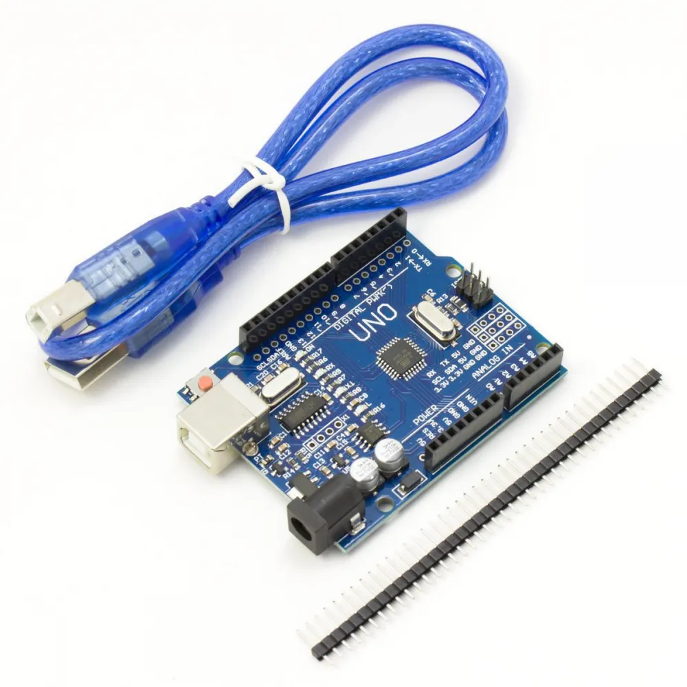
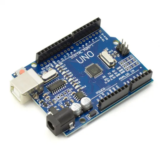
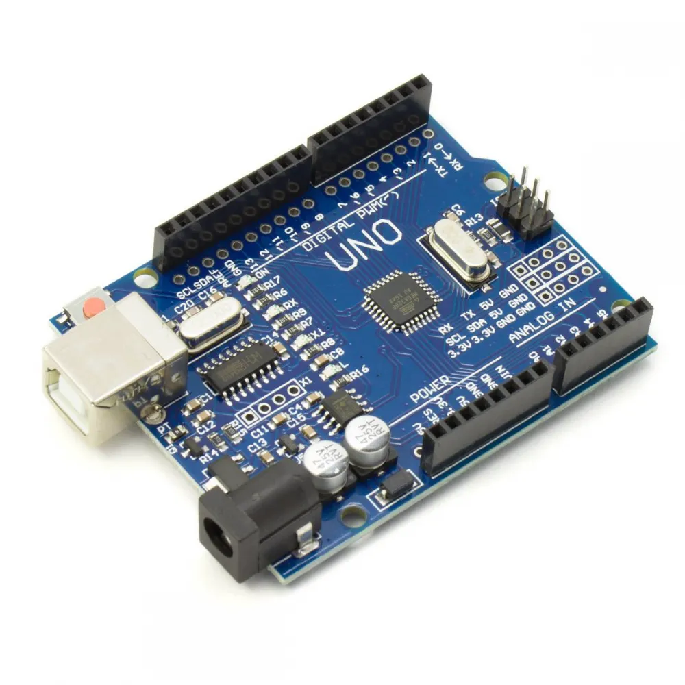
Arduino UNO R3 compatible development board based on a 16 MHz 8-bit ATmega328P-AU microcontroller and fitted with a CH340G USB-to-serial converter.
It retains the 5 V logic, pin arrangement and form factor of the UNO R3 platform, making it suitable for learning, prototyping, sensors, simple automation and GRBL projects with an appropriate expansion board.
Main features
- ATmega328P-AU microcontroller with 8-bit AVR architecture.
- 16 MHz operating frequency.
- 5 V logic and digital input/output levels.
- 14 digital pins, six of which support PWM output.
- Six analogue inputs with a 10-bit ADC.
- UART, I2C/TWI and SPI interfaces.
- USB-B connector and CH340G USB-to-serial converter.
- DC power jack, VIN input and 5 V and 3.3 V pins.
- ICSP connector for direct ATmega328P programming.
- Reset button and power, transmit, receive and D13 indicators.
- Headers arranged for UNO R3-format shields, subject to each shield's pinout and power requirements.
Technical specifications
| Feature | Value |
|---|---|
| Type | UNO R3 compatible development board |
| Microcontroller | ATmega328P-AU, soldered TQFP package |
| Architecture | 8-bit AVR |
| Clock | 16 MHz |
| Flash memory | 32 KB total; available program space depends on the installed bootloader |
| SRAM | 2 KB |
| EEPROM | 1 KB |
| Logic voltage | 5 V |
| Digital I/O | 14: D0-D13 |
| PWM | 6 channels: D3, D5, D6, D9, D10 and D11 |
| Analogue inputs | 6: A0-A5, 10-bit ADC |
| GPIO design current | Up to 20 mA per pin while also observing the microcontroller's aggregate limits |
| USB-to-serial | CH340G through USB-B |
| Recommended initial supply | 5 V USB-B |
| Conservative external supply | Regulated 7-9 V through the jack or VIN for light loads |
| Form factor | UNO R3-style mechanical and header arrangement |
| Programming | USB bootloader or ISP programming through ICSP |
The 40 mA absolute limit shown in the ATmega328P datasheet is not a recommended operating current. Design outputs for 20 mA or less and reduce the load when several pins are active simultaneously.
Pin functions and communications
| Function | Pins | Notes |
|---|---|---|
| UART | D0/RX and D1/TX | Shared with the CH340G; a connected peripheral may interfere with sketch uploads. |
| External interrupts | D2 and D3 | Suitable for events requiring prompt response. |
| PWM | D3, D5, D6, D9, D10 and D11 | Pulse-width modulation rather than a continuous analogue voltage. |
| SPI | D10/SS, D11/MOSI, D12/MISO and D13/SCK | Also available from the ICSP header. |
| I2C/TWI | A4/SDA and A5/SCL | The R3-format SDA/SCL positions duplicate the same signals. |
| Analogue | A0-A5 | 10-bit ADC; they can also be used as digital GPIO. |
| Built-in LED | D13 | Useful for the first Blink example test. |
Safe power supply
Use the included USB-B cable for initial commissioning. USB supplies 5 V and allows the board to be programmed and used with the serial monitor.
The UNO R3 architecture also supports an external supply through the jack or VIN. As the exact regulator and its thermal capability are not documented for this compatible board, we recommend a regulated 7 to 9 V supply and light loads.
- A higher input voltage forces the linear regulator to dissipate more heat.
- Do not power motors, relays, solenoids, heaters or LED strips from the on-board regulator.
- Never apply 12 or 24 V directly to the 5 V, 3.3 V or input pins.
- The 5 V pin bypasses the input regulator: use it only with a stable regulated 5 V supply, verified polarity and a method that prevents USB back-feeding.
- For 3.3 V peripherals, verify whether their inputs tolerate 5 V signals and use level conversion where required.
Programming with Arduino IDE
- Install a current version of Arduino IDE 2.
- Install or update Arduino AVR Boards from Boards Manager.
- Connect the board with a USB data cable.
- Select
Tools > Board > Arduino AVR Boards > Arduino Uno. - Select the serial port created by the CH340G.
- Open
File > Examples > 01.Basics > Blinkand upload the sketch. - Check that the
LLED blinks and that the RX/TX indicators operate during transfer.
If the operating system does not create a serial port, first test another port and USB data cable. When an additional driver is required, obtain the CH340/CH341 driver only from the official WCH page.
If the sketch compiles but does not upload
- Confirm that Arduino Uno and the correct port are selected.
- Temporarily disconnect any circuit attached to D0/RX, D1/TX and RESET.
- Close serial monitors and applications that may be holding the port open.
- Try pressing reset as the upload begins if auto-reset is not operating correctly.
- If the port works but the bootloader is damaged, it can be restored through ICSP with a compatible programmer; do not change fuses or bootloader without verifying the procedure for ATmega328P and UNO.
Shield compatibility
The headers follow the UNO R3 layout, but a shield must not be considered compatible merely because it fits physically. Before purchasing or connecting an expansion board, check:
- 5 V logic level and supply requirements;
- used pins and possible conflicts between modules;
- current drawn from the 5 V and 3.3 V rails;
- height and possible collision with the USB-B connector, jack or headers;
- library support for AVR and ATmega328P;
- the Flash and SRAM required by the project.
Using it with CNC Shield V3 and GRBL
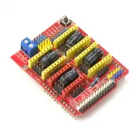
This board can be used with the CNC Shield V3 for UNO R3 in small CNC routers, plotters or engravers running a GRBL version compatible with the ATmega328P.
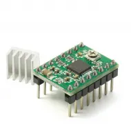
The CNC Shield requires drivers such as the A4988 or DRV8825, plus a suitable motor power supply. Motors are not powered from USB or from the board's GPIO pins.
Before moving an axis, configure the firmware, insert every driver in the correct orientation, set its current, verify microstepping, endstops and cooling, and test at low speed. Never connect or remove motors or drivers while powered.
Mounting and protection
The board follows the UNO R3 mechanical format, approximately 69 × 54 mm including connector projections. Very tight enclosures should be checked against the actual unit, allowing for the USB-B connector, jack, header height and mounting-hole positions.
- Mount the board on spacers and prevent solder joints from touching a conductive surface.
- Disconnect both power and USB before changing wiring.
- Join grounds when circuits powered from separate supplies communicate, unless purpose-designed isolation is provided.
- Protect inputs from overvoltage, reverse polarity, inductive noise and electrostatic discharge.
- Use a flyback diode, transistor, MOSFET or suitable driver for inductive loads.
Contents
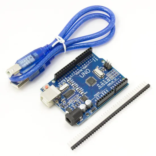
The pictured set includes:
- One UNO R3 compatible board with ATmega328P-AU and CH340G.
- One USB A-to-B cable.
- One breakaway male pin-header strip for assemblies or expansions that require soldering.