

- Stock: Out of Stock
- Model: DLC32

MKS DLC32 is a 32-bit ESP32 controller for building or upgrading GRBL-compatible diode laser engravers and small CNC machines. It combines USB, Wi-Fi and web control, offline operation from a microSD card, three stepper-driver channels and dedicated TTL/PWM laser and DC spindle outputs.
It suits projects that need a compact, flexible board with replaceable StepStick drivers and support for an optional MKS touchscreen. Correct use requires firmware that matches the exact board revision, kinematics and display, together with independently designed machine-safety measures.
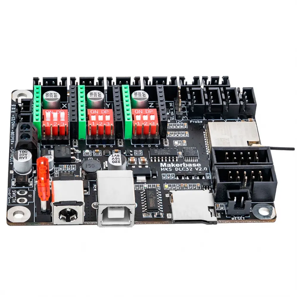
Main features
- ESP32-WROOM-32U: 32-bit dual-core microcontroller running at up to 240 MHz, with Wi-Fi and an external-antenna connection.
- 8 MB flash memory and 520 KB RAM according to MKS.
- 12 or 24 V DC input, plug-in fuse and status indication for the main voltage rails.
- Three motion channels: X, Y and Z, with StepStick sockets and external-driver signals.
- Four motor connectors: X, Y1, Y2 and Z; Y1 and Y2 share the same Y driver.
- Laser control: supply output and 0–5 V TTL/PWM control, plus a two-wire supply-voltage PWM output.
- Small DC spindle control and the option to command a suitable external power stage.
- PC, local-web and offline operation using a microSD card.
- Declared compatibility with LaserGRBL and LightBurn; commercial software licences are not included.
- EXP1/EXP2 for MKS TS24 or TS35 displays with matching firmware.
Technical specifications
| Item | Specification |
|---|---|
| MCU | ESP32-WROOM-32U, dual core, 32 bit, up to 240 MHz |
| Memory | 8 MB flash; 520 KB RAM |
| Power input | 12–24 V DC; published maximum input current of 5 A |
| USB | CH340 USB serial; the board also requires DC power |
| Motion | 3 driver channels: X, Y and Z; X, Y1, Y2 and Z motor connectors |
| Drivers | StepStick sockets with DIP microstep selection and EN/STEP/DIR/GND external-driver signals |
| Laser TTL | 0–5 V PWM; 1 kHz default, configurable from 1 to 10 kHz according to the MKS manual |
| On-board laser supply | Published maximum: 25 W at 12 V or 50 W at 24 V |
| On-board DC spindle output | Published maximum: 10 W at 12 V or 20 W at 24 V |
| Inputs | X/Y/Z limits, probe and I2C expansion; check voltage, polarity and firmware |
| Storage | TF/microSD; MKS recommends 4–16 GB, FAT32, class 4 or 10 |
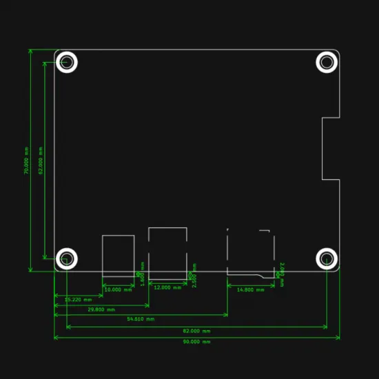
| Dimensions | 90 × 70 mm; 82 × 62 mm mounting-hole centres |
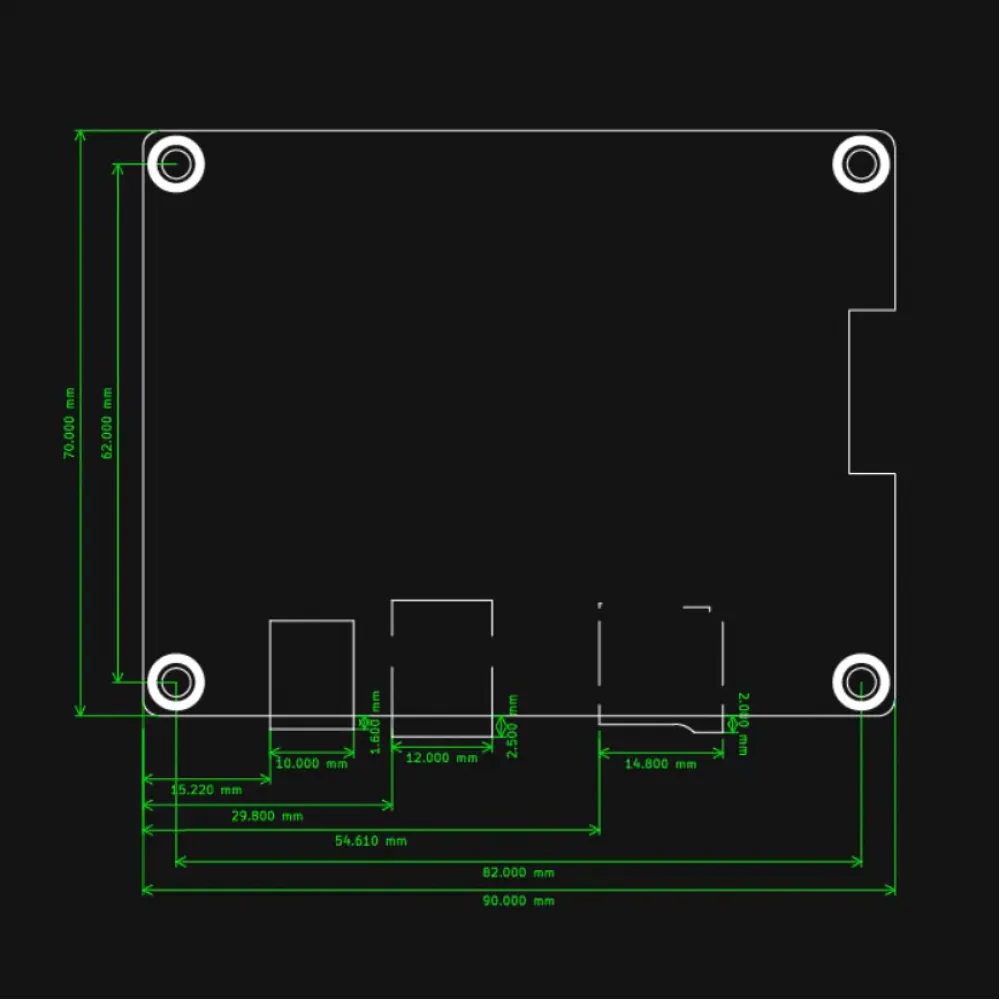
Board revision: check it before wiring
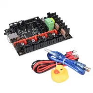
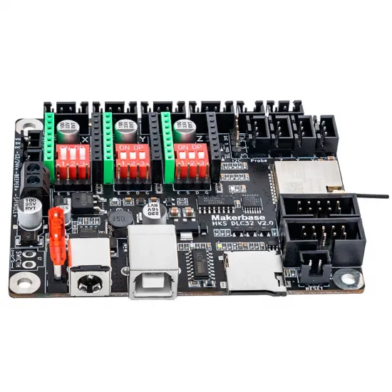
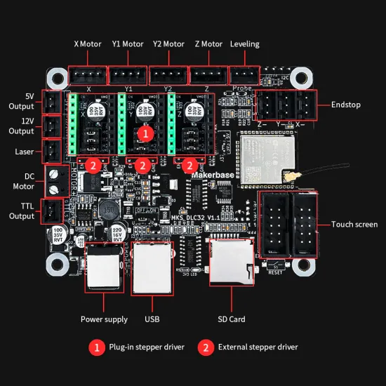
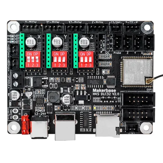
The photographs in this listing show an MKS DLC32 V2.0. MKS has also released V2.1 revisions with physical and silkscreen changes. Before installing, flashing or following a pinout, locate the revision printed on your own board and use only its matching documentation. A V1.1 diagram must not be applied to a V2.x board.
Stepper drivers and motors
The DLC32 has sockets for three plug-in drivers: X, Y and Z. It can use stand-alone StepStick drivers such as the A4988 or DRV8825, provided orientation, pinout, microsteps, voltage and current adjustment are all checked before power-up.
Y1 and Y2 are wired in parallel to the same Y channel. They are useful for two motors that must move together, but they do not provide independent control or automatic gantry squaring. EN, STEP, DIR and GND signals are available for higher-current external drivers; the external stage must accept those levels and use suitable power and protection.
Laser connection
The three-pin output provides supply voltage, ground and a 0–5 V TTL/PWM control signal. If the board is powered from 24 V, the supply pin outputs 24 V; it does not automatically regulate the voltage for a 12 V laser head. MKS publishes direct-supply limits of 25 W at 12 V and 50 W at 24 V.
- Confirm the laser module's supply voltage and current.
- Check the actual V, GND and signal order; do not rely only on wire colours or a similar-looking connector.
- Verify that the control input accepts 0–5 V TTL/PWM and shares ground with the board.
- Set frequency and power scale only according to the installed module and firmware.
- Make the first test at minimum power, with the machine enclosed and safety measures active.
The two-wire PWM output follows the input-supply voltage and is not equivalent to a 0–5 V TTL input. Incorrect wiring can damage both the module and the controller.
CNC controller use
MKS firmware includes a CNC mode and probe input. The direct spindle output is limited by the manufacturer to 10 W at 12 V or 20 W at 24 V, so it is suitable only for small DC motors. A more powerful spindle requires a correctly rated external stage; never connect a mains or high-power spindle directly to this output.
The CNC firmware is described as beta in the MKS documentation. Bench-test its functions and limits before relying on it in a complete machine.
Firmware, GRBL and control software
MKS supplies different firmware for Cartesian laser, CoreXY laser and CNC machines, with additional variants for V1.x/V2.x boards and TS24/TS35 displays. The file must match all four variables. Flashing a similarly named binary is not a safe selection method.
- Save the current configuration with
$$before changing parameters. - For laser use with GRBL 1.1,
$32=1enables Laser Mode. $30must match the maximum S value configured in LaserGRBL or LightBurn; there is no universal value for every setup.- Check steps per millimetre, travel, directions, limits and origin with the laser disabled.
- The USB interface uses CH340. Install its driver only if the operating system does not recognise the board.
The web interface and Wi-Fi control are intended for a trusted local network. Do not expose the controller directly to the Internet or rely on the network as the only way to stop the machine.
Display, microSD and offline work
EXP1 and EXP2 support the MKS TS24/TS35 displays specified by the manufacturer. Not every 3.5-inch screen is equivalent: the correct model, cable orientation and firmware are required. The display is sold separately.
For offline work, MKS recommends a 4–16 GB FAT32 microSD card, class 4 or 10, and documents .NC, .GC and .GCODE files. Keep the source files and perform a dry-run before starting the job.
Electrical installation
- Use a 12 or 24 V DC power supply with enough margin for the board, motors, laser and accessories.
- The manual specifies a 5 A maximum input current; the 10 A fuse does not turn the board into a continuous 10 A output.
- Size wires, connectors, fuses and cooling for the actual load.
- Never connect or disconnect motors or drivers while powered.
- USB does not replace the board's DC supply.
- Check polarity and the absence of short circuits before first power-up.
Laser and machine safety
The DLC32 is a controller, not a complete safety system. Its external reset connector resets the microcontroller, but must not be treated by itself as a safety-rated emergency stop or a physical power disconnect.
- Enclose and contain the beam; add interlocks, an accessible power cut-off and suitable warning labels.
- Use certified eye protection for the laser wavelength and optical density; glasses do not replace an enclosure.
- Install extraction appropriate to the material and do not process substances that create corrosive or hazardous fumes.
- Keep flammable material away and provide suitable fire-control equipment.
- Never leave the machine running unattended.
It is for you if
- You are building or upgrading a two- or three-axis GRBL laser engraver.
- You want USB, Wi-Fi, local-web and offline control on one platform.
- You prefer replaceable StepStick drivers or need external-driver signals.
- You can check schematics, configure firmware and design the machine protections.
It is not for you if
- You need a finished, certified, ready-to-use laser product.
- You need four independent axes or automatic squaring with two separate Y drivers.
- You want to power a high-power spindle or a laser exceeding the board limits directly.
- You cannot confirm the revision, pinout, voltage and signal type of every component.
Package contents
- 1 × MKS DLC32 board.
Drivers, display, microSD card, USB cable, power supply, motors, laser, spindle, limit switches, wiring, enclosure and safety equipment are not considered included unless an order option explicitly states otherwise.
Documentation and video
See the official MKS DLC32 repository and select the files for your exact revision.