Menu
Your Cart

Mellow FLY 4-output CANBus and power distributor, 5–24 V

Mellow FLY 4-output CANBus and power distributor, 5–24 V
New
Mellow FLY 4-output CANBus and power distributor, 5–24 V
11.95€
Ex Tax: 9.88€
  • Stock: 10
  • Model: MELLOW-CAN-EXP
Fast shipping from Spain
Delivery from 24 hours and free shipping available in mainland Spain.
Stock on hand
Shipped quickly from Spain, with a full VAT invoice.
Secure & flexible payment
Pay by card, PayPal or bank transfer.
Expert technical support
Over 10 years helping customers with components and compatibility.

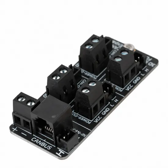
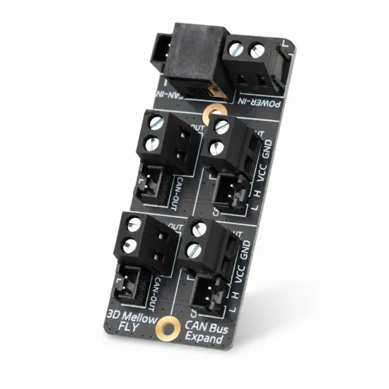
The Mellow FLY CANBus Expand organises connections for up to four CAN boards and distributes their power from one common point. It is useful for 3D printers with toolhead electronics, multi-tool projects and installations where accessible, labelled connections are preferable to scattered wire splices.

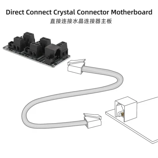
It combines screw terminals for power, 2.54 mm XH connectors for CAN and an RJ11 input. It distributes connections: it is not a USB-to-CAN adapter, motor controller or voltage converter.

A central connection point for tidier wiring

Mellow develops the FLY electronics family, including mainboards, communication modules and toolhead boards. This distributor supports that type of installation by keeping the power connections physically separate from the CAN signal connectors and providing four labelled outputs.

Accessible connections make wiring inspection and board replacement easier. This does not mean tools can be connected or disconnected with the printer powered on: switch off and disconnect the supply before changing connections.

Technical specifications

Brand and familyMellow / FLY CANBus Expand
FunctionCAN and power distribution for up to four boards on its outputs
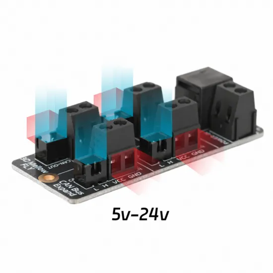
Input voltage5–24 V DC
Output voltageSame as input; no voltage regulation or step-down
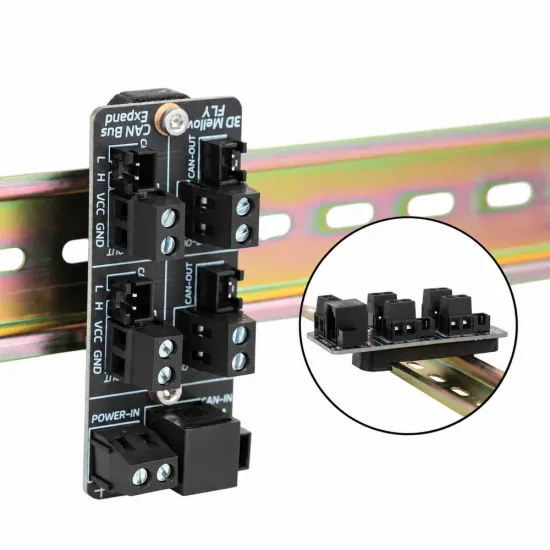
CAN connectionsOne RJ11 and five 2.54 mm XH connectors: input and four outputs
Power connectionsFive two-pole screw terminals: one input and four outputs
MountingMounting holes; DIN-rail installation with a suitable printed bracket

Compatibility: bus, connectors and power

Mellow lists FLY SHT36, SB2040 and FLY Pi / Super systems as applications. Other CAN boards may also be used if the wiring, supply voltage and communication protocol are compatible.

For a Voron 2.4, Trident or another customisable printer, suitability depends on the fitted electronics, rather than the printer name. It does not add CAN to a board without that capability or turn a Raspberry Pi into a CAN interface: the system still requires an appropriate CAN adapter or bridge.

A matching connector does not guarantee a matching pinout. Follow the board's CAN H / CAN L and VCC / GND markings. Its RJ11 carries CAN using the manufacturer's assignment; it is neither a telephone nor an Ethernet port. Do not use a telephone cable without checking conductor correspondence.

Power: one common voltage for all four outputs

Connect a suitable DC supply to the input terminal, observing polarity. Every power output receives the same voltage. With a 24 V input, the outputs supply 24 V: they cannot directly power a Raspberry Pi requiring 5 V.

All connected boards must accept the selected voltage. Size the supply, wiring, protection and connections for the combined loads passing through the distributor. A toolhead heater powered through it contributes to that load. Use appropriate electrical protection; do not treat this board as an individually protected power distributor.

Keeping the CAN bus stable

The four outputs share communication; they are not four independent CAN networks. Keep a clear main bus route and branches as short as practical. A distributor does not remove the bus limitations: long star branches can cause reflections and communication errors.

Use a twisted pair for CAN H and CAN L. Klipper's CAN installation guidance calls for two 120 Ω terminating resistors at the physical ends of the bus, not one resistor on every connected device. Check any built-in termination on adapters and boards, including resistors that cannot be disabled.

With the entire installation powered off, approximately 60 Ω measured between CAN H and CAN L is consistent with two 120 Ω terminations in parallel. This is a useful check, not proof that the pinout, topology or firmware is correct.

Using it with Klipper

The distributor does not require its own MCU section in printer.cfg. Configure the host's CAN interface and each connected controller board with the appropriate firmware, bus speed and individual UUID. Do not copy another printer's UUID.

To identify a new, uninitialised board once the CAN interface is operational, Klipper provides the following tool. Replace can0 if your interface has another name:

~/klippy-env/bin/python ~/klipper/scripts/canbus_query.py can0

Run it only during commissioning, with the printer idle. It is not a periodic connection test and must not be run during a print. An already initialised board may not appear in its results; that does not mean it is disconnected.

Using it with RepRapFirmware

It can distribute connections in a compatible RepRapFirmware CAN installation, as described by Mellow. Functional compatibility depends on the controllers, their revisions and firmware: it does not turn a Klipper-configured board into a RepRapFirmware expansion. Follow the documentation for your controller and expansions. The distributor itself does not require firmware flashing.

Mounting and initial checks

  1. Switch off and disconnect the entire installation before mounting or changing cables.
  2. Secure the PCB without contacting metal parts. Use a suitable printed bracket for DIN-rail mounting and keep the connectors accessible.
  3. Verify polarity, each device's permitted voltage and CAN cable continuity, especially when using RJ11.
  4. Check the two bus terminations and avoid unnecessarily long branches.
  5. Start with one connected device and verify communication before extending the installation. Provide strain relief so cable movement cannot pull on connectors.

It is for you if…

  • You already have a CAN interface and want to organise power and communication for one or more boards.
  • You are building a printer with toolhead electronics or multiple tools.
  • You prefer accessible, labelled connections to scattered wire splices.

It is not for you if…

  • You need a USB-CAN adapter, a 24-to-5 V converter or a mainboard.
  • You require independent CAN networks or want to mix incompatible protocols without adaptation.
  • You want a drop-in replacement without checking pinout, voltage and termination.

Included

1 Mellow FLY CANBus Expand board with mounted connectors. Controller boards, cables and the printed DIN-rail bracket shown in installation examples are not included.

Installation documentation

FLY CANBus documentation · Klipper CAN and termination guidance · Klipper CAN communication troubleshooting.

Write a review

Note: HTML is not translated!
Bad Good
Captcha