Menu
Your Cart

Mellow FLY ADXL345 USB-C accelerometer with RP2040 for Klipper

Mellow FLY ADXL345 USB-C accelerometer with RP2040 for Klipper
New
Mellow FLY ADXL345 USB-C accelerometer with RP2040 for Klipper
9.99€
Ex Tax: 8.26€
  • Stock: 5
  • Model: MELLOW-ADXL345-USB
Fast shipping from Spain
Delivery from 24 hours and free shipping available in mainland Spain.
Stock on hand
Shipped quickly from Spain, with a full VAT invoice.
Secure & flexible payment
Pay by card, PayPal or bank transfer.
Expert technical support
Over 10 years helping customers with components and compatibility.

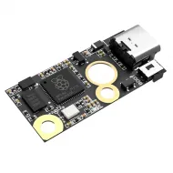
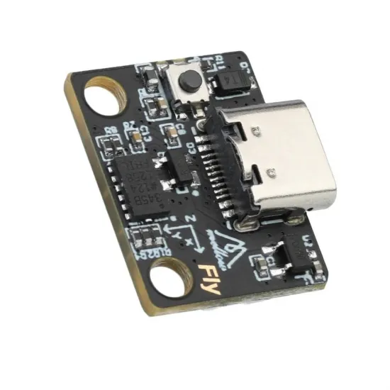
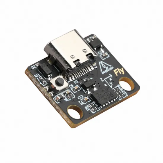
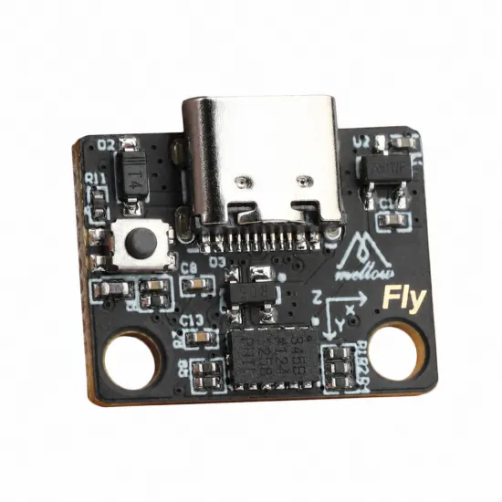
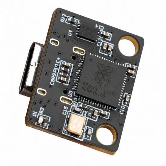
The Mellow FLY ADXL345 USB is a compact accelerometer for measuring a 3D printer's resonances with Klipper and tuning Input Shaper. It combines a three-axis ADXL345 sensor and an RP2040 microcontroller on a USB-C board: measurements are acquired locally and sent over USB to the computer running Klipper.

It provides a practical way to examine your printer's mechanical response without wiring a separate SPI accelerometer directly to a Raspberry Pi's GPIO pins. Measurements help select suitable compensation for each axis and reduce ringing or ghosting, the ripples that follow sudden changes in direction.

Why choose this Mellow FLY board?

  • Integrated sensor and controller: no separate microcontroller is needed to connect the ADXL345 to the host.
  • USB-C connection: a USB data cable carries power and communications, avoiding an external SPI wiring harness to the computer.
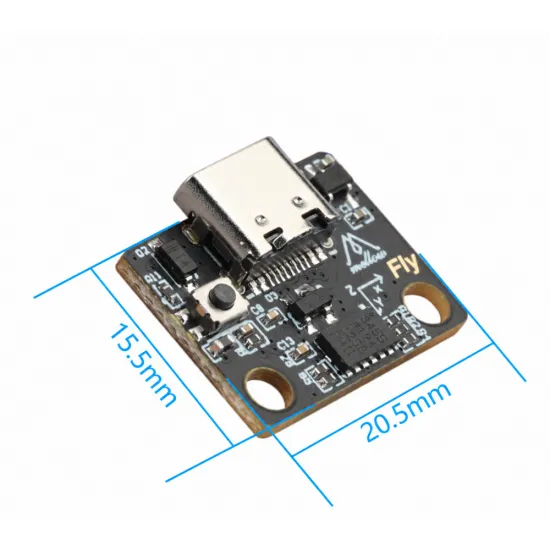
  • Compact footprint: nominal PCB dimensions of 20.5 × 15.5 mm, with two mounting holes and printed axis orientation marks.
  • Board-specific documentation: Mellow provides a Klipper configuration identifying this ADXL345 board's internal sensor pins.
  • Temporary or permanent installation: install it for calibration and remove it afterwards, retaining the Input Shaper settings and disabling the accelerometer configuration while disconnected.

USB simplifies installation but does not replace setup: the host must run Klipper, recognise the device and have the resonance measurement tools installed.

Technical specifications

Brand and familyMellow FLY ADXL345 USB
SensorADXL345, three-axis accelerometer
MicrocontrollerRaspberry Pi RP2040, dual-core ARM Cortex-M0+, 133 MHz
Host connectionUSB, USB-C connector on the board
Power supplyPowered from the host USB port; do not connect to the printer's 12 or 24 V supply
Nominal PCB dimensions20.5 × 15.5 mm; these are not the assembly height or installation envelope
Reference firmwareKlipper
USB cableNot included; use a data-capable cable, not a charge-only cable

Printer and host compatibility

Suitable for Klipper projects with an available host USB port, including a Raspberry Pi, Mellow FLY Pi or a computer supporting your Klipper installation. It does not require spare SPI GPIO pins on the printer's mainboard.

It can be used on a Voron 2.4, Voron Trident, Voron V0 or VzBot running Klipper, provided you have a suitable mount and can connect the sensor to the host. It is also useful on an Ender 3 or another moving-bed printer converted to Klipper: the toolhead and bed are measured separately. These examples do not imply that a printer-specific mount is supplied or that the board works with every printer's stock firmware.

This is not a bed levelling probe, filament sensor or CANBus module. This version uses an ADXL345: do not copy a [lis2dw] configuration from a similar-looking USB board.

Mounting for useful measurements

Attach the sensor rigidly to the moving part you want to measure. A flexible bracket, a loose board or a cable under tension can affect the results. Check cable clearance throughout the travel and prevent the PCB, contacts and components from touching metal or hot surfaces.

  • CoreXY: a toolhead mount allows its X and Y motion resonances to be measured.
  • Moving-bed printer: mount the sensor on the toolhead for X and on the bed for Y, repeating mounting and measurement for each axis. One board can be used for both stages.
  • Orientation: use the PCB markings as a reference and adjust axes_map if the sensor orientation differs from the printer axes. There is no universal mapping for every bracket.

Install or reposition the sensor with the machine stopped and disconnected when handling electronics. Do not measure with an unsecured board or attach it to a hot area.

Klipper setup

Before calibration, check that the host has the analysis dependencies listed in Klipper's resonance measurement guide. A working printing installation does not necessarily include all the resonance analysis tools.

1. Identify the board and prepare firmware if needed

Connect the board to the host using a USB data cable. From the host terminal, check its identifier:

ls -l /dev/serial/by-id/

With compatible Klipper firmware installed, a device path should be identifiable. If it is missing, first check the cable, port and USB detection. Do not assume every unit arrives with the firmware required by your installation.

If compilation is needed, Mellow's direct-flashing procedure uses RP2040, No bootloader and USB/USBSERIAL communication. Save the compilation settings used for your printer's mainboard before changing them. In the Klipper directory:

cd ~/klipper
make menuconfig
make

Select Raspberry Pi RP2040/RP235x, processor rp2040, no bootloader offset and USB communication. To enter flashing mode, disconnect accelerometer power, hold its BOOT button and connect it to the host. In this procedure, the RP2040 boot device is identified as 2e8a:0003. With firmware freshly compiled for this accelerometer:

make flash FLASH_DEVICE=2e8a:0003

Verify the device before flashing: do not leave another RP2040 in boot mode or flash accelerometer firmware onto the printer's mainboard. This procedure is for direct flashing without an additional bootloader; do not mix it with Katapult instructions using a different offset. Reconnect the board afterwards and retrieve its actual device path.

2. Add the board-specific ADXL345 configuration

You can keep the settings in a separate file, such as accelerometer.cfg, included from printer.cfg. The following is a template that must be adapted before restarting: replace the complete identifier and all three coordinates with actual, safe values for your printer. The placeholders between < > are not valid configuration values.

[mcu adxl]
serial: /dev/serial/by-id/<ACTUAL_ACCELEROMETER_IDENTIFIER>

[adxl345]
cs_pin: adxl:gpio9
spi_software_sclk_pin: adxl:gpio10
spi_software_mosi_pin: adxl:gpio11
spi_software_miso_pin: adxl:gpio12

[resonance_tester]
accel_chip: adxl345
probe_points:
    <SAFE_X>, <SAFE_Y>, <SAFE_Z>

Add [include accelerometer.cfg] to the main file if you used that filename. The [mcu adxl] section defines an additional microcontroller: it does not replace the printer mainboard's [mcu] section. If an accelerometer or [resonance_tester] already exists, merge the settings without duplicate sections. Adjust axes_map to the actual sensor orientation when needed.

3. Check the sensor and measure resonances

After saving and restarting Klipper, check the sensor with the machine stationary:

ACCELEROMETER_QUERY
MEASURE_AXES_NOISE

If the sensor does not respond, reports an identification error or shows abnormal noise, resolve the problem before measuring. Check the configuration, cable and mounting rigidity. Stationary readings include gravity: all three axes are not expected to read zero.

Home the printer, check that the test point and travel are clear, then calibrate. On a CoreXY with the sensor correctly mounted on the toolhead, SHAPER_CALIBRATE can measure both axes. On a moving-bed printer, measure X with the sensor on the toolhead using SHAPER_CALIBRATE AXIS=X, then Y with the sensor on the bed using SHAPER_CALIBRATE AXIS=Y.

The test deliberately causes vibration. Keep tools and loose objects away and stop if abnormal motion occurs. Review the recommendations before running SAVE_CONFIG. Klipper proposes compensation and provides acceleration guidance, but does not automatically turn those recommendations into a safe max_accel setting.

Making the most of the results

Input Shaper reduces ripples associated with mechanical resonances while balancing compensation against motion smoothing. It does not repair loose pulleys, backlash, incorrectly tensioned belts, uneven extrusion or every surface artefact. It is not closed-loop correction during printing and does not guarantee a particular printing speed.

Keep sensible acceleration settings and revisit calibration after changing toolhead mass, belt tension, frame components or other parts affecting resonance. When removing the accelerometer, disable its included file and corresponding sections while retaining the saved [input_shaper] settings: a configured but disconnected MCU can prevent Klipper from starting.

It is for you if…

  • You run Klipper and want to tune Input Shaper using measurements from your own printer.
  • You prefer USB over wiring SPI to the host's GPIO pins.
  • You want a compact board for temporary installation on the toolhead or bed.

It is not for you if…

  • You need an accessory that works without configuration with any stock firmware.
  • You need a bed levelling probe or CANBus sensor.
  • You expect to eliminate every printing defect without checking mechanics and other settings.

Contents and additional requirements

One Mellow FLY ADXL345 USB board. USB cable not included. Setup requires a data-capable USB cable suitable for the host, a suitable mounting arrangement and a working Klipper installation. A model-specific mount is not promised for the printers mentioned.

For further installation and analysis details, see the Klipper resonance measurement guide and the resonance compensation documentation.

Write a review

Note: HTML is not translated!
Bad Good
Captcha