


- Stock: 2
- Model: MELLOW-E3U-H723

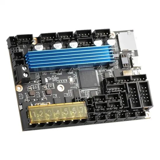
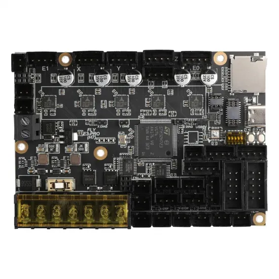
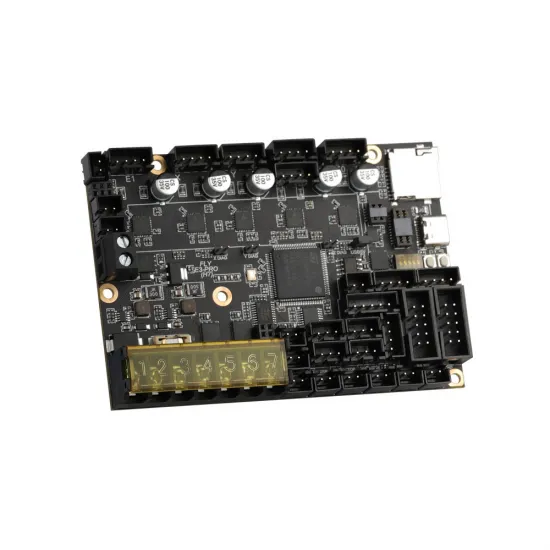
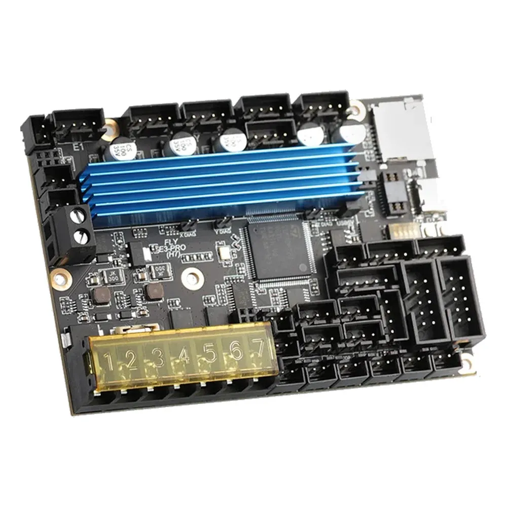
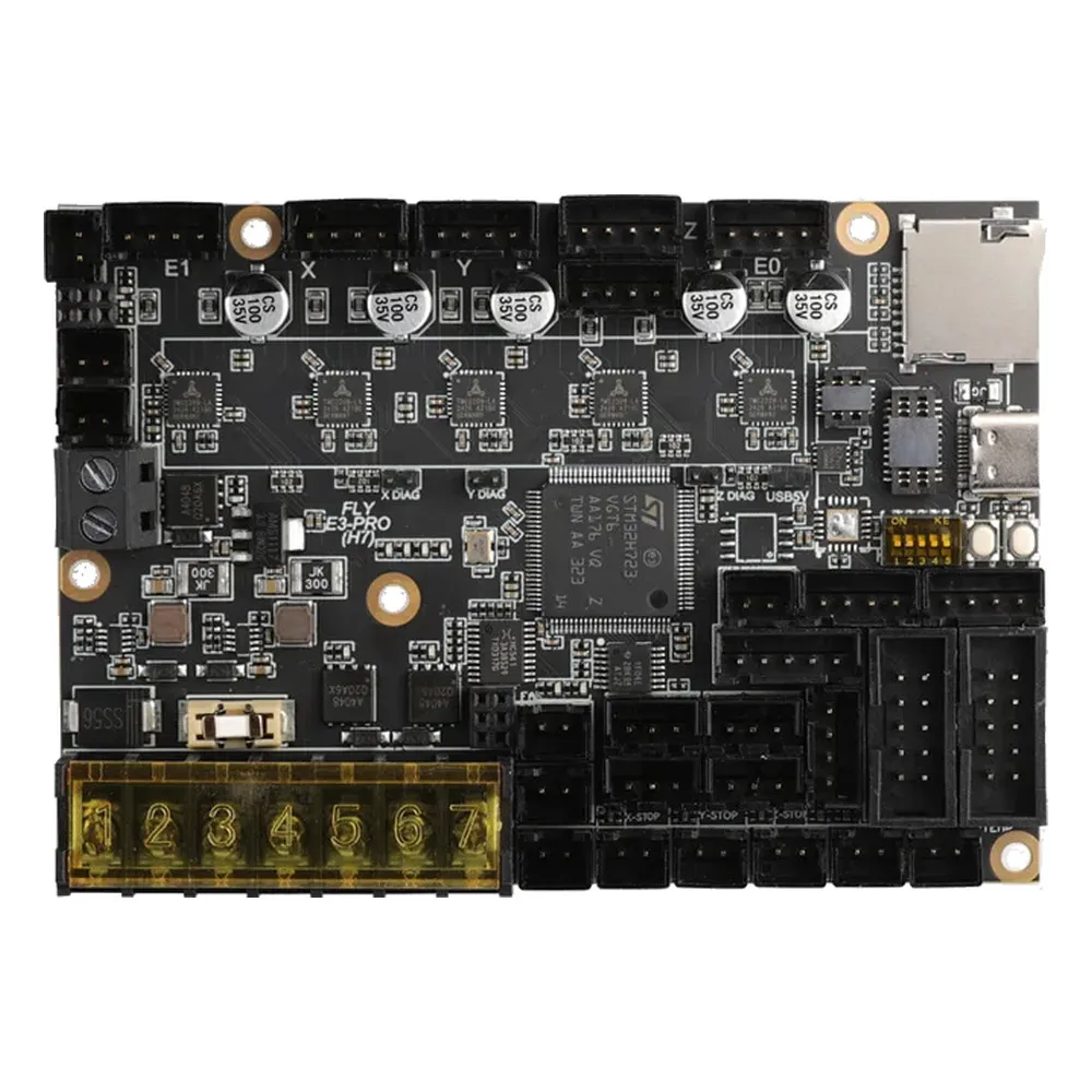
The Mellow FLY E3 PRO Ultra H723 is a 32-bit 3D printer mainboard with five integrated TMC2209 drivers, an STM32H723 processor, USB-C and CAN connectivity. It combines the compact Ender 3-style footprint with resources for two extruders, bed-leveling probes and expansion through a toolhead board.
This product is the standard Ultra version, not Ultra Max. It includes the driver heatsink and connection accessories. It is a useful choice for replacing printer electronics or building a Klipper or RepRapFirmware project, with firmware and wiring adapted to the actual machine.
What this mainboard adds
- STM32H723 ARM Cortex-M7, up to 550 MHz: a powerful platform for the control firmware. Actual printing speed also depends on mechanics, extrusion and tuning; it cannot be calculated simply from the processor clock.
- Five UART-controlled TMC2209 drivers: set motor current and driver parameters through firmware without purchasing five separate driver modules. Integrated drivers simplify assembly and avoid the orientation issues of plug-in modules.
- Included heatsink: helps remove heat from the drivers. Keep the electronics enclosure ventilated, especially at higher motor currents or inside a heated chamber.
- CAN and USB-C: choose a conventional USB connection or plan a Klipper CAN installation with electronics at the toolhead.
- Four controlled fans and three heating channels: resources for part cooling, hotend and electronics cooling, plus a bed and two hotend heaters.
- Replaceable fan MOSFETs: small VS3622e modules each control two fan outputs. This design makes servicing that circuit possible without replacing the complete mainboard.
StealthChop can prioritize quiet operation, while SpreadCycle may suit certain speed and load conditions better. Choose the mode for the actual motor and machine: quiet operation does not replace correct current settings or guarantee the elimination of all vibration.
Technical specifications
| Model | Mellow FLY E3 PRO Ultra H723, standard version |
|---|---|
| Microcontroller | STM32H723, 32-bit ARM Cortex-M7, up to 550 MHz |
| Drivers | 5 integrated TMC2209 drivers with UART; X, Y, Z, E0 and E1 positions |
| Operating supply | 12 or 24 V DC; supply both positive inputs and the common negative |
| Heaters | 1 heated-bed output and 2 hotend outputs |
| Temperature sensing | 3 analog inputs with 2.2 kΩ pull-up resistors |
| Fans | 4 controlled two-pin outputs; replaceable MOSFET modules |
| Endstops | 3 X/Y/Z inputs; configurable DIAG connections for sensorless homing |
| Communication and expansion | USB-C, CAN, microSD, EXP1/EXP2, serial-display port, probe connector and optional ESP32 header |
| Nominal PCB dimensions | 100.7 × 70.2 mm; also allow space for the heatsink, terminals and cables |
| Documented firmware | Klipper and the TeamGloomy-maintained RepRapFirmware port for STM32 |
Printer and project compatibility
The manufacturer positions this mainboard as an upgrade for Creality Ender 3, Ender 3 Pro, Ender 5 and Ender 5 Pro, and for projects such as Voron 0 and other DIY printers. On classic Ender machines, its footprint and mounting layout can make replacing the original electronics easier.
This is integration compatibility, not a universal plug-and-play replacement. Check the printer revision, mounting points, operating voltage, motor and thermistor connectors, display and cable lengths. Matching connectors do not necessarily mean matching pinouts or protocols. Do not automatically extend this compatibility to Ender 3 V2, S1, V3 or other generations.
A Voron 0 or another CoreXY machine needs the appropriate kinematics configuration and usually a suitable bracket or electronics enclosure. The board has no Raspberry Pi or other Linux computer onboard: Klipper requires an external host. Input Shaper and Pressure Advance are configured and tuned in Klipper; resonance measurements also require a compatible accelerometer, which is not included.
Five drivers and two Z sockets: an important distinction
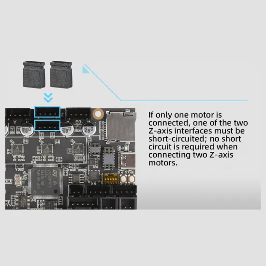
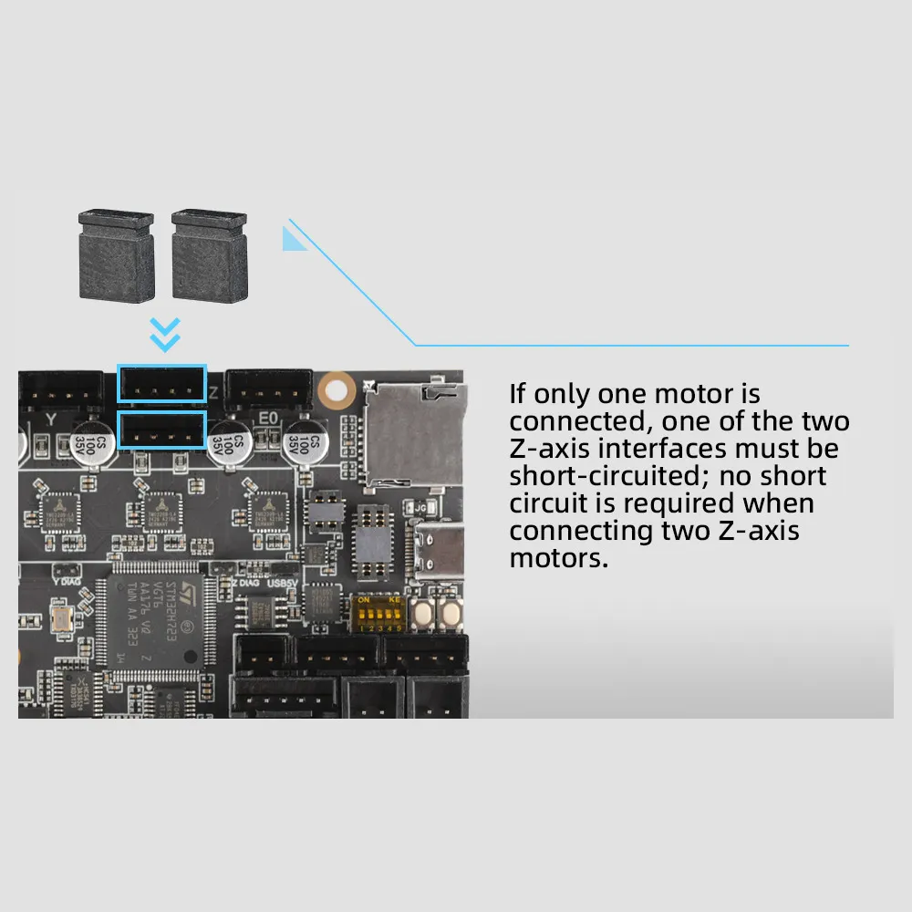
X, Y, Z, E0 and E1 are five independent driver positions. However, the two sockets connected to the Z driver are wired in series. They allow two Z motors to share one driver, not to adjust their heights independently.
- Two Z motors: connect both to the Z sockets following the wiring diagram; do not fit the jumpers intended to close an unused socket.
- One Z motor: fit the jumpers on the unused socket exactly as shown by the manufacturer, closing both corresponding pairs. Leaving it empty or fitting one jumper arbitrarily is not sufficient.
- Two independent Z motors: a single-extruder project can reassign the E1 driver to the second Z motor with suitable firmware and wiring. This uses the fifth driver; it does not create a sixth independent channel.
Do not connect or disconnect motors while the board is powered. For sensorless homing, fit the corresponding axis DIAG jumper and tune sensitivity and homing speed. On a Z axis that travels towards the bed, a probe or dedicated endstop is generally a more appropriate choice than relying solely on stall detection.
Power supply and outputs: preparing the wiring
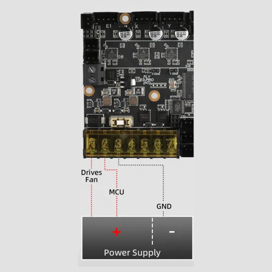
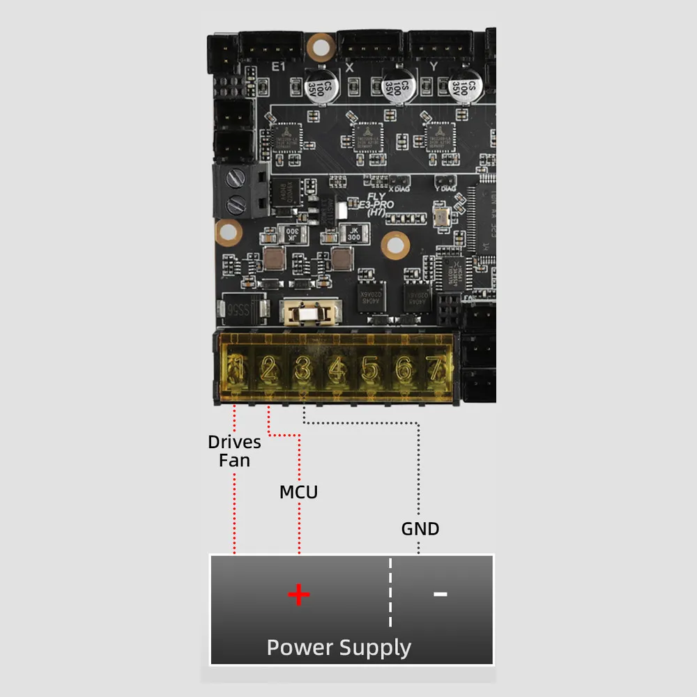
On the numbered terminal block, 1 is the load positive for motors, heaters and fans, 2 is the electronics positive, and 3 is GND, the common negative. In a conventional installation, terminals 1 and 2 receive positive power from the same 12 or 24 V supply, using connections and protection sized for their respective loads.
This separation can support a controlled load shutdown while keeping the logic powered, with the required additional circuit. Both positive inputs need power even when no relay is used. The mainboard must not be connected directly to mains voltage and does not, by itself, guarantee print recovery after a power failure.
The manufacturer publishes these per-output limits. They are documented upper ratings, not a recommendation to operate continuously at the limit or a combined capacity that can be added without checking the installation.
| Output | At 24 V | At 12 V |
|---|---|---|
| Heated bed | 15 A | 7.5 A |
| Each hotend heater | 6 A | 3 A |
| Each fan | 1 A | 0.5 A |
Check consumption, wire gauge, fuses, ventilation and terminal tightening. Heaters, beds and fans must match the supply voltage: PWM control does not turn a 24 V fan output into a 5 V supply. Loads beyond the admissible rating require a suitably protected external controller. A mains-powered bed needs a different electrical installation and must not connect directly to these outputs.
Temperature: NTC and PT1000 with a 2.2 kΩ pull-up
The board has three temperature inputs for the bed and hotends. Their reference resistance is 2,200 Ω, which matters when configuring Klipper: a configuration for a 4,700 Ω input gives incorrect readings.
For a generic 100 kΩ NTC with beta 3950, use Klipper's Generic 3950 sensor type and pullup_resistor: 2200. Other sensors need their actual curves. Within an [extruder] section otherwise completed for your printer, the E0 temperature fragment would be:
# Temperature fragment only, not a complete printer configuration
heater_pin: PA2
sensor_pin: PA4
sensor_type: Generic 3950
pullup_resistor: 2200
A compatible PT1000 sensor can also use an analog input with sensor_type: PT1000 and the same 2,200 Ω pull-up. PT1000 is not PT100: the standard version does not include the PT100 and K-type thermocouple converters fitted to Ultra Max.
Before enabling a heater, check that the room-temperature reading is plausible, belongs to the correct sensor and rises when that sensor is gently warmed. Set temperature limits and thermal protection for the actual hotend, bed and sensor; do not disable checks to hide an incorrect reading. Then perform the appropriate PID tuning.
Installing Klipper on the H723
With Klipper installed on the host, compile the mainboard firmware using make menuconfig. For a conventional USB connection, the manufacturer’s H723-specific guide specifies:
| Build option | USB setting |
|---|---|
| Enable extra low-level configuration options | Enabled |
| Micro-controller Architecture | STMicroelectronics STM32 |
| Processor model | STM32H723 |
| Bootloader offset | 128KiB bootloader |
| Clock Reference | 25 MHz crystal |
| Communication interface | USB (on PA11/PA12) |
- Save the settings and run
makein the Klipper directory. - Copy
out/klipper.binto the root of a FAT32 microSD card of up to 32 GB, renaming itfirmware.bin. Check that Windows has not added an extra extension. - With the board powered off, insert the card, then power on and wait at least the ten seconds indicated by the manufacturer. A renamed
FLY.CURfile confirms that the bootloader performed the update. - Connect USB to the host and run
ls /dev/serial/by-id/*. Use the board’s actual identifier in[mcu], not an identifier copied from another printer. - Configure kinematics, motors, endstops, sensors and outputs, checking each function before moving all axes or enabling heaters.
These build options apply to the documented H723 bootloader. If a different bootloader has been installed, check its offset before compiling. For update or recovery questions, see Mellow’s board-specific firmware guide.
Klipper pin reference
This table identifies GPIOs, not the correct direction, current or motion calibration for your printer. Enable is normally prefixed with ! in Klipper because it is active-low. Direction inversion depends on the mechanical installation.
| Connector | STEP | DIR | EN | UART |
|---|---|---|---|---|
| X | PE3 | PE2 | PE5 | PE4 |
| Y | PD1 | PD0 | PE1 | PE0 |
| Z | PA15 | PD7 | PC2 | PA8 |
| E0 | PD4 | PD3 | PD6 | PD5 |
| E1 | PC13 | PC0 | PC15 | PC14 |
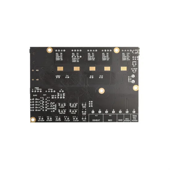
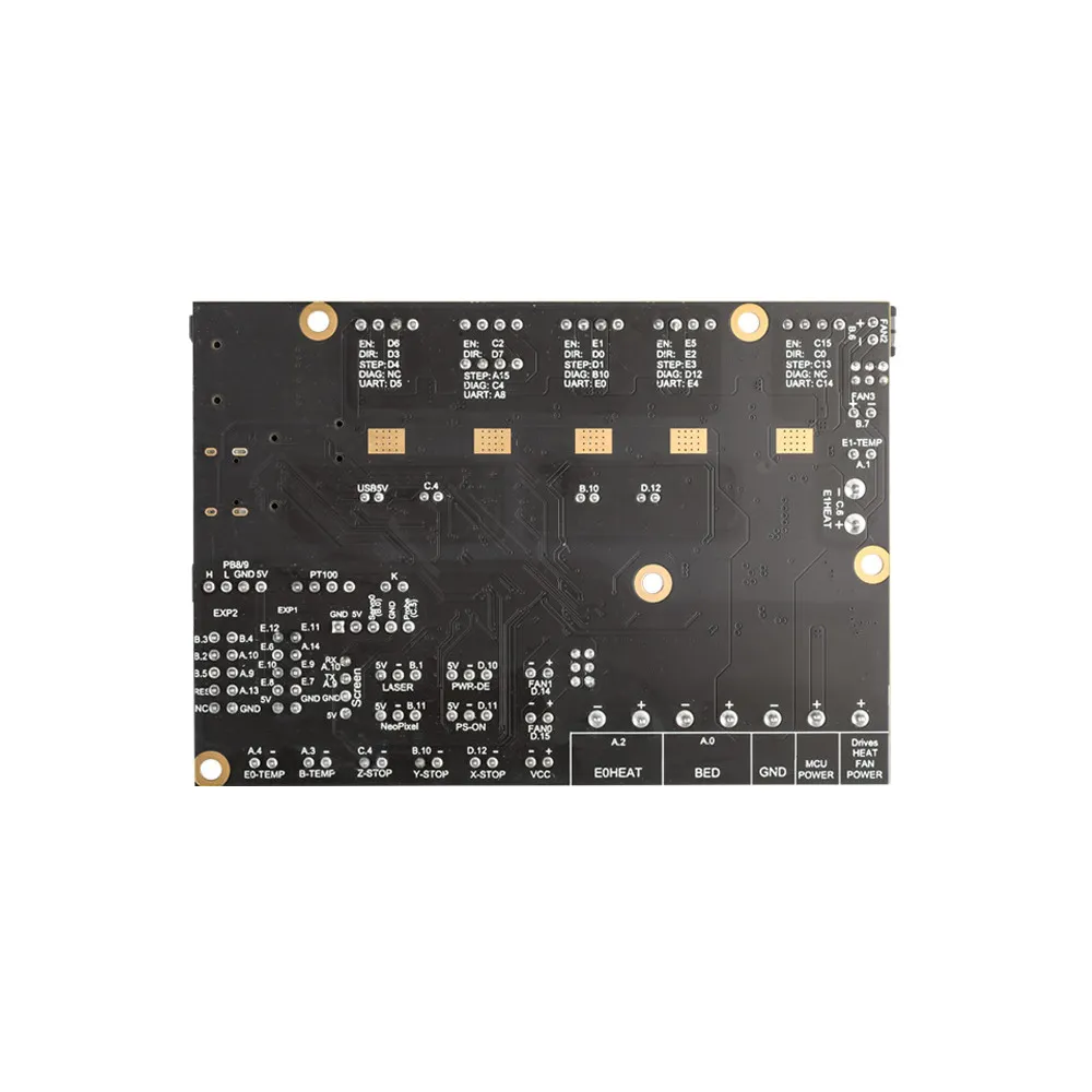
Other signals: bed PA0 / sensor PA3; E0 heater PA2 / sensor PA4; E1 heater PC6 / sensor PA1; FAN0 PD15, FAN1 PD14, FAN2 PB6 and FAN3 PB7; X endstop PD12, Y PB10 and Z PC4; BLTouch-style control PB0 and probe input PC5. The schematic specifies 0.11 Ω TMC2209 sense resistors.
Signal pins must not receive the power-supply voltage. Check the pinout and electrical level of each probe. A 12/24 V-powered inductive sensor may require output-level adaptation; never connect that voltage directly to a GPIO.
CAN bus and toolhead expansion
For Klipper, the board can be compiled as a USB-to-CAN bridge. Keep STM32H723, the 128 KiB bootloader and 25 MHz crystal, but select USB to CAN bus bridge (USB on PA11/PA12) and CAN bus (on PB8/PB9). The manufacturer’s default rate is 1,000,000 bit/s; the host and all devices on the same bus must use the same bitrate.
A setup using a Mellow FLY SHT36 V3 Plus can reduce the number of long wires routed to the toolhead. It requires compatible Klipper firmware on both boards, host configuration, appropriate power and CAN wiring. Sharing a manufacturer or having a CAN connector is not enough.
Connect CAN-H to CAN-H and CAN-L to CAN-L, use a twisted pair, and fit a 120 Ω termination at each end of the bus rather than at every device. The fifth DIP switch enables this mainboard’s termination; enable it only when the board is a bus endpoint. In bridge mode, Klipper communicates with the mainboard using its canbus_uuid, not the serial port used for conventional USB mode. Refer to the Klipper CAN documentation for host networking and node identification.
RepRapFirmware and optional WiFi
TeamGloomy provides E3 Ultra H723 documentation for RepRapFirmware 3.5 and later. It supports planning a standalone installation with the appropriate ESP32 module and Duet Web Control, or SBC integration according to the selected mode. The ESP32 is not included and is not needed for Klipper over USB.
Select the STM32 firmware for e3ultra_h723 and generate a configuration adapted to the printer. The preset includes five drivers and a 2,200 Ω thermistor reference resistance. RRF output names and driver numbering must not be copied directly from Klipper: use this port’s configurator and pin tables.
WiFi operation additionally requires compatible ESP32 firmware and Duet Web Control versions, plus sys/config.g and the machine macros on the microSD. The TeamGloomy H723 guide explains the file structure and connection procedure. Its CAN-FD expansion uses the RRF protocol and is not interchangeable with attaching a toolboard configured for Klipper CAN.
Dimensions and package contents
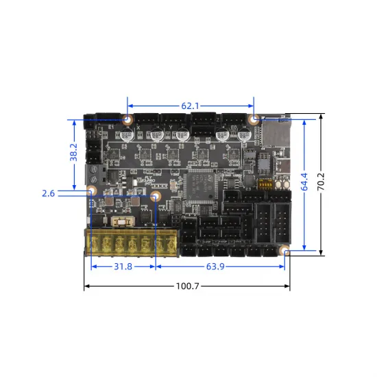
The nominal PCB size is 100.7 × 70.2 mm. The mechanical drawing specifies 62.1 mm horizontally between the two upper mounting points, 38.2 mm vertically between the upper-left and side point, and 64.4 mm vertically between the upper-right and lower point. Additional position dimensions are 2.6, 31.8 and 63.9 mm; interpret them using the drawing's reference lines, not as mounting-hole diameters. When designing an enclosure, allow additional space for projecting connectors, the heatsink and cable bends; PCB dimensions do not describe the complete installation envelope.
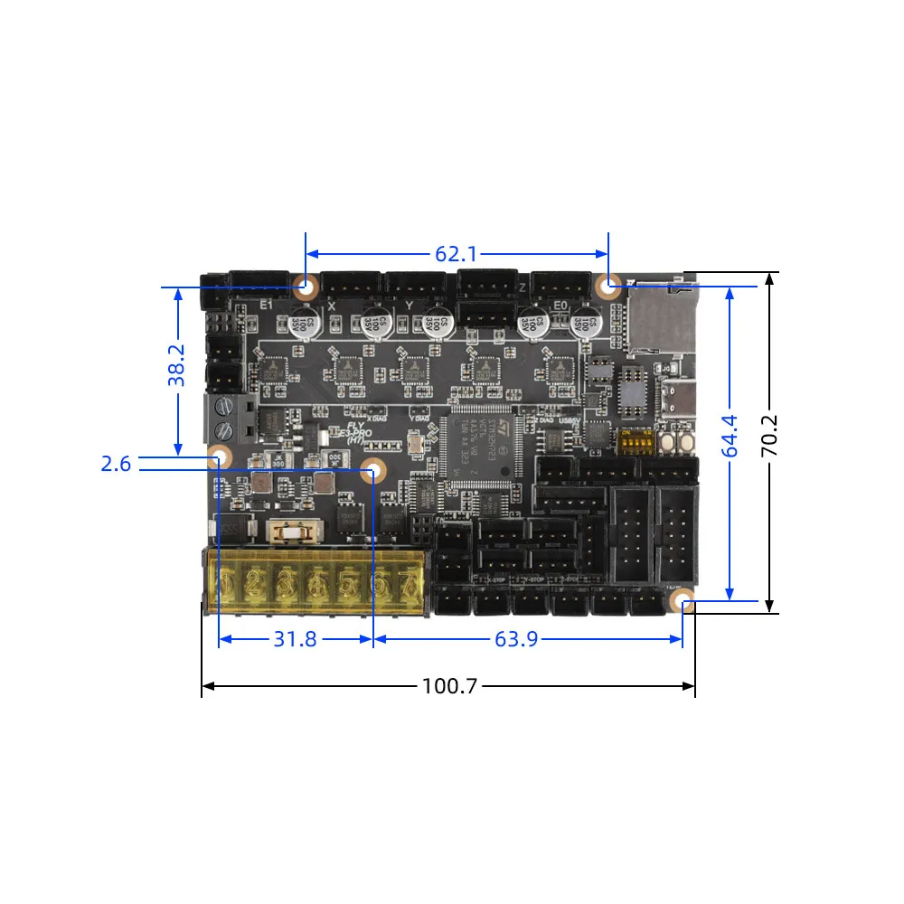
Includes: one standard FLY E3 PRO Ultra H723 mainboard, heatsink, USB cable, connectors, jumpers and terminal blocks. ESP32 WiFi module, Linux host, display, power supply, motors and sensors are not included.
This is for you if…
- You want to upgrade a classic Ender or build a DIY printer with five integrated drivers and configurable firmware.
- You want USB now and the option of a Klipper CAN toolhead later.
- You need two hotends or want to reassign E1 to a second independent Z axis in a single-extruder project.
- You can adapt wiring, compile or install the appropriate firmware and carry out initial checks.
This is not for you if…
- You need a universally ready-to-use mainboard without configuring it or checking connections.
- Your project needs more than five independent motors or interchangeable high-voltage driver modules.
- You expect Klipper without an additional host, WiFi without an ESP32 or Ultra Max’s PT100/K-type converter inputs.
- You expect independent Z leveling from the two Z sockets without reallocating another driver.
Before the first print
- With power disconnected, check polarity, jumpers, wiring and mounting on standoffs. Prevent contact with the enclosure.
- Verify communication, motor current, rotation direction and endstop operation before a complete homing procedure.
- Check temperature readings and test each heater/sensor pairing separately. Keep thermal protection enabled.
- Test fans and the probe, then perform PID and machine calibrations before unattended printing.
For installation and future expansion, consult the FLY E3 Ultra technical documentation and the RepRapFirmware integration reference.