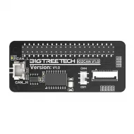


- Stock: 8
- Model: Portable-Input-Shaper

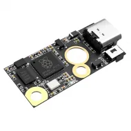
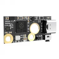
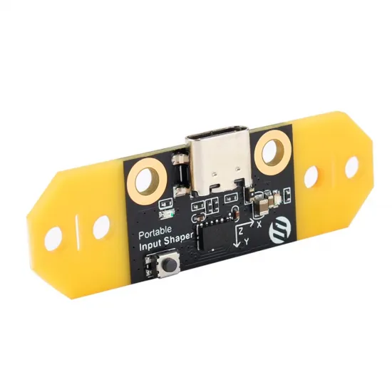
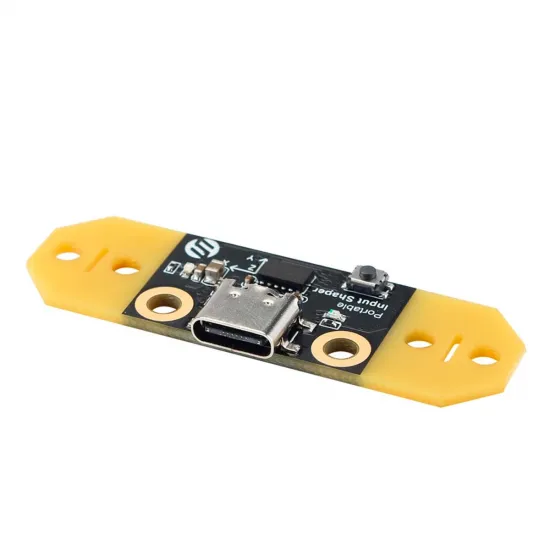
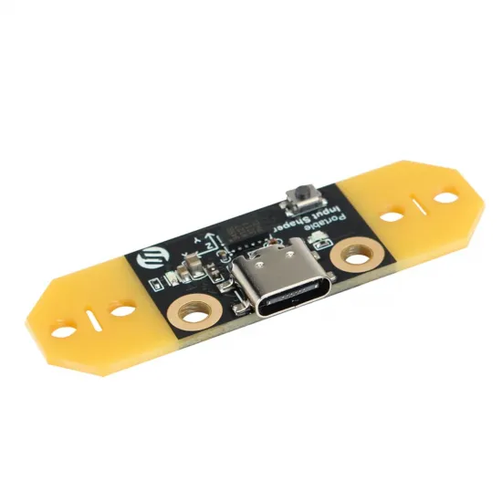
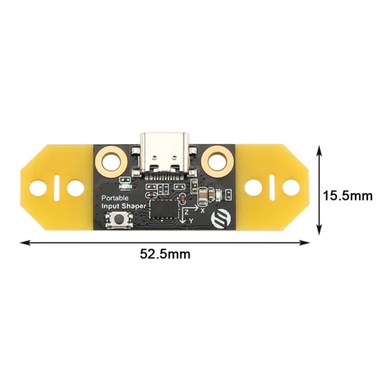
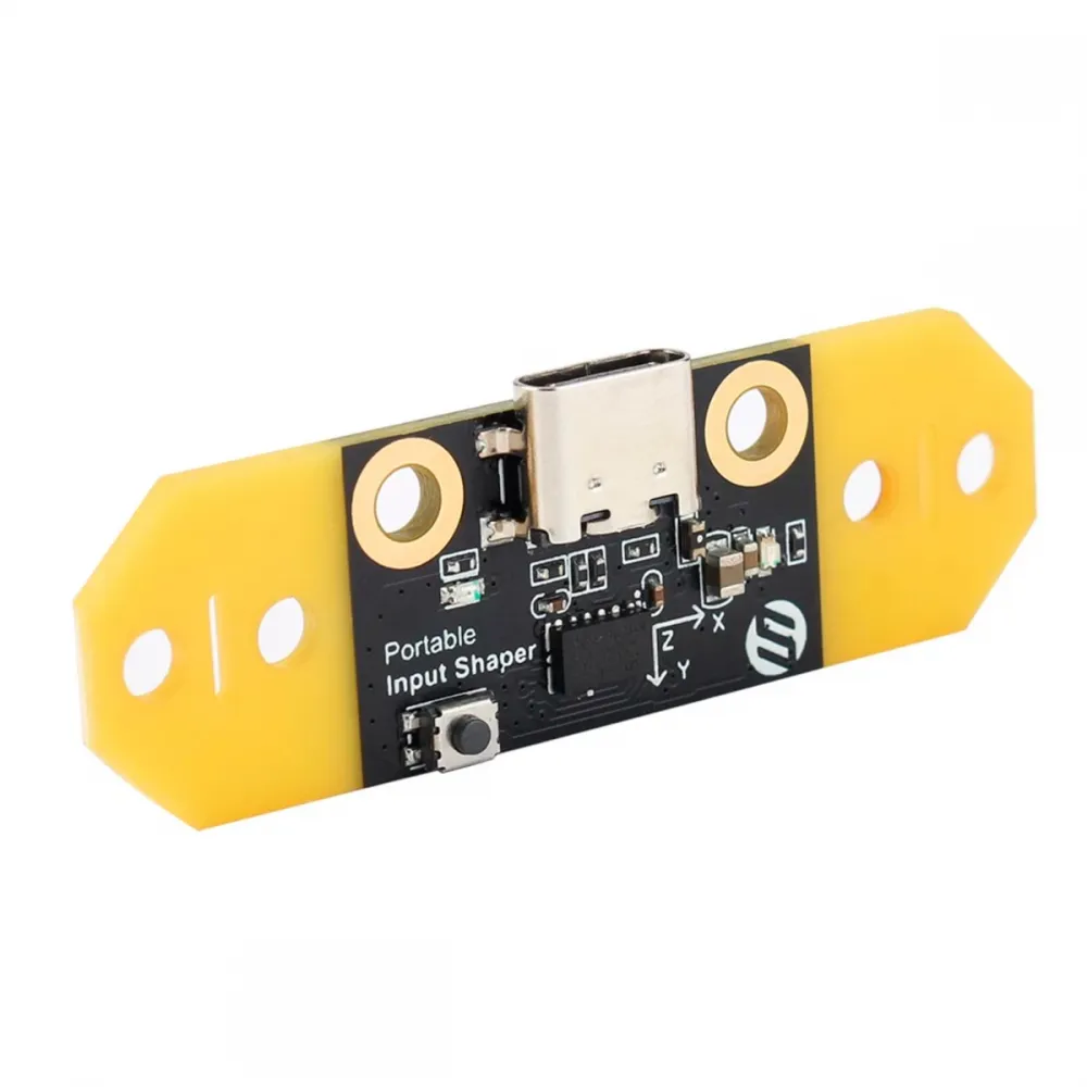
The FYSETC Portable Input Shaper is a portable resonance measuring device for 3D printers running Klipper. It combines an RP2040 microcontroller and a three-axis ADXL345 accelerometer on the same board, connecting to the Klipper host through USB-C as a dedicated secondary MCU.
It measures the printer's resonance frequencies and helps calculate input-shaper parameters that reduce ringing or ghosting. Once the resulting values have been stored, the module can be removed and used on another printer; it does not need to remain installed during printing.
What it adds to 3D-printer calibration
- Physical resonance measurement: records actual acceleration on the moving assembly during a frequency sweep.
- Automatic calibration: Klipper can compare several filters and suggest input-shaper type and frequency for X and Y.
- USB connection: avoids carrying the accelerometer's SPI signals over a long cable to a Raspberry Pi or main controller.
- Portable use: it can be configured in a separate file, connected for calibration and removed afterwards.
- Versatile mounting: FYSETC documents Voron AfterBurner and StealthBurner installations and provides resources for other toolheads.
Input shaping compensates for part of a machine's vibration through its motion profile, but it cannot repair loose screws, incorrectly tensioned belts, damaged wheels, binding rails or play in the toolhead. Mechanical condition should be checked before interpreting calibration results.
Technical specifications
| Feature | Value |
|---|---|
| Manufacturer | FYSETC |
| Microcontroller | Raspberry Pi RP2040 |
| Accelerometer | ADXL345, three axes |
| Host interface | USB-C, operating as a secondary Klipper MCU |
| Internal interface | SPI between RP2040 and ADXL345 |
| Power | 5 V from USB with internal 3.3 V regulation |
| Klipper sampling rate | Up to 3200 Hz for ADXL345; Klipper's recommended default for resonance measurement |
| Sensor ranges | Software-selectable ±2 g, ±4 g, ±8 g and ±16 g |
| Sensor resolution | Up to 13 bits; approximately 3.9 mg/LSB in full-resolution mode |
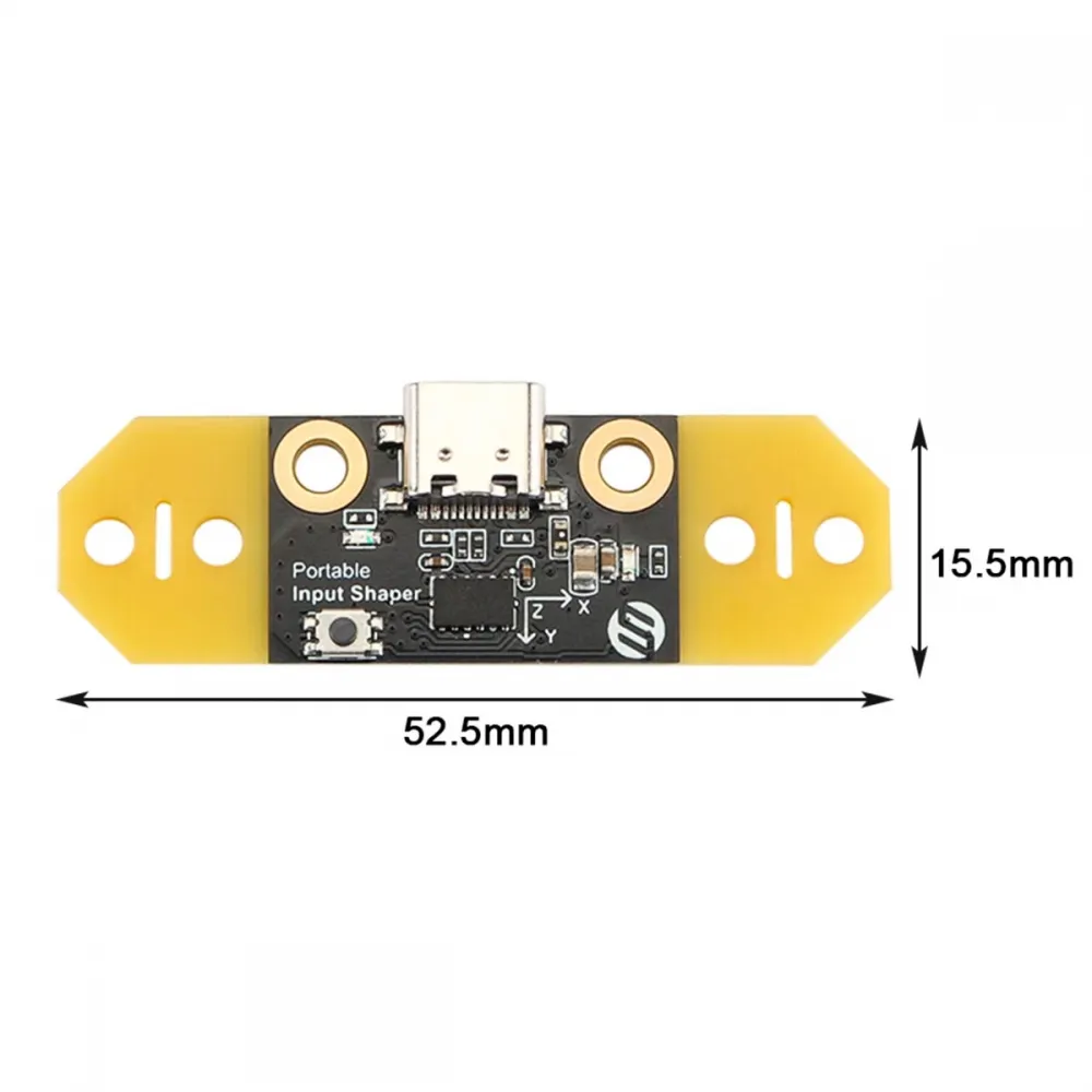
| Dimensions | 52.5 × 15.5 mm |
| Controls and indicators | BOOT button and status LED |
| Documented firmware | Klipper |
Compatibility requirements
It can be used conditionally on 3D printers running Klipper where the host has a USB port capable of carrying data. It is suitable for Raspberry Pi and other Linux computers used as Klipper hosts, provided the system recognises the RP2040 as a stable serial device.
It does not depend directly on the printer-controller model because it communicates with the host over USB, but the following conditions must be met:
- Klipper must allow an additional USB MCU.
- The USB-C cable must carry data; a charge-only cable will not work.
- The firmware flashed to the module must match the current Klipper installation.
- The mounting point must be rigid, electrically isolated and clear of the machine's travel.
- Test coordinates must remain inside the actually reachable area.
Where to mount the accelerometer
CoreXY, Voron and other machines with X/Y toolhead motion
On a CoreXY printer such as Voron 2.4 or Voron Trident, the module can be rigidly attached to the toolhead for X and Y measurements. FYSETC shows installations for AfterBurner and StealthBurner, but space, fasteners and exact toolhead revision must still be checked.
Cartesian bed-slinger printers
On an Ender-3, Prusa i3 or similar printer, X normally belongs to the toolhead and Y to the bed. For representative readings, fit the module to the toolhead while calibrating X and rigidly attach it to the bed while calibrating Y. It must not be left loose or simply placed on the build surface.
Delta and other kinematics
On a Delta it is normally mounted on the effector. Klipper supports tests on custom axes, but directions and commands should be taken from the documentation for that specific kinematics.
The board carries printed sensing-axis directions. Klipper can swap or invert them through axes_map, so the arrows do not have to physically coincide with the printer's X, Y and Z axes; the actual orientation must, however, be declared correctly.
Host preparation
Measurement and automatic analysis require NumPy, Matplotlib and the libraries specified by the current Klipper version. On a standard Linux installation, the official guide uses:
sudo apt update
sudo apt install python3-numpy python3-matplotlib libatlas-base-dev libopenblas-dev
~/klippy-env/bin/pip install -v "numpy<1.26"
~/klippy-env/bin/python -c 'import numpy;'
The final command should return without an error. Paths or dependencies may differ on printer-manufacturer-managed images, so the documentation for the installed distribution should take precedence.
Compiling and flashing Klipper to the RP2040
Avoid using an old UF2 binary downloaded from a third party. FYSETC warns that the module must run firmware compatible with the host's Klipper version.
- Open the Klipper installation and run:
cd ~/klippermake cleanmake menuconfig - Select Raspberry Pi RP2040 architecture and USB communication. Do not enable advanced options or an additional bootloader unless a future FYSETC revision explicitly requires it.
- Build with
make. The file is normally generated as~/klipper/out/klipper.uf2. - Disconnect the module, hold its BOOT button and connect USB-C.
- Release the button when the
RPI-RP2drive appears, then copyklipper.uf2to it. - After the board reboots, identify it with:
ls /dev/serial/by-id/*
Keep the complete path beginning in a form similar to usb-Klipper_rp2040_.... This identifier is unique to each module and must not be copied from an example.
Safe Klipper configuration
The following block uses FYSETC's published pins. Replace the serial identifier and coordinates with values from the actual printer:
[mcu pis]
serial: /dev/serial/by-id/usb-Klipper_rp2040_YOUR_IDENTIFIER

[adxl345]
cs_pin: pis:gpio13
spi_software_sclk_pin: pis:gpio10
spi_software_mosi_pin: pis:gpio11
spi_software_miso_pin: pis:gpio12
axes_map: x,-z,y

[resonance_tester]
accel_chip: adxl345
probe_points:
    X_CENTRE, Y_CENTRE, SAFE_Z
axes_map: x,-z,y corresponds to FYSETC's reference orientation. Change it if the board is rotated or fitted to another face. The probe point should be close to the usable centre, slightly above the bed and leave several centimetres of travel margin.
The block can be saved as pis.cfg and added to printer.cfg with:
[include pis.cfg]When the module is removed, temporarily comment out this include or the related sections so that Klipper does not attempt to connect to an absent MCU.
Checks before measuring
- Confirm that the board and cable are securely held and clear of the nozzle, heaters, belts and fans.
- Run
ACCELEROMETER_QUERY. It should return X, Y and Z readings including approximately the acceleration due to gravity. - Run
MEASURE_AXES_NOISE. Klipper states that values around 1 to 100 are typical; figures near 1000 or above require checking power, sensor, fans or mounting. - Move the machine slowly and confirm that the USB cable cannot tighten or catch.
- Switch fans off for calibration and secure any panel, spool or part that could vibrate.
Step-by-step calibration
To measure each axis separately:
TEST_RESONANCES AXIS=X
TEST_RESONANCES AXIS=Y
Automatic tuning can also be run by axis:
SHAPER_CALIBRATE AXIS=X
SHAPER_CALIBRATE AXIS=Y
On a bed-slinger, calibrate X with the sensor on the toolhead, stop the machine, rigidly move it to the bed and calibrate Y. Other kinematics may keep it on the toolhead when that assembly represents both motions.
M112. If motion becomes violent, stop, inspect the mechanics and conservatively reduce accel_per_hz according to the current Klipper documentation.
Klipper reports frequencies, suggested filter type, estimated remaining vibration, smoothing and a theoretical acceleration limit. If the results are reasonable, SAVE_CONFIG adds the parameters to [input_shaper].
Understanding the results
- Resonance frequency: depends on moving mass, stiffness, belts, mounting, position and mechanical condition.
- Shaper type: ZV, MZV, EI, 2HUMP_EI and 3HUMP_EI offer different compromises between vibration reduction and smoothing.
- Smoothing: a more aggressive filter may reduce ringing but can round detail and restrict useful acceleration.
- Calculated acceleration: it estimates a smoothing-related limit, not an automatically safe mechanical recommendation. Motors, frame, hotend and flow rate impose separate limits.
There is no need to recalibrate before every print. Repeat the measurement after changes that can alter machine dynamics, such as belts, toolhead, extruder, rails, bed, frame or moving mass. Klipper advises against overly frequent intensive calibrations because they increase wear and may loosen components.
Troubleshooting
| Symptom | Recommended checks |
|---|---|
Missing from /dev/serial/by-id | USB data cable, host port, power and correct flashing. |
| Klipper reports an MCU protocol mismatch | Rebuild and reflash from the same current Klipper installation. |
Invalid adxl345 id | Review SPI configuration, firmware and possible sensor failure. |
| High noise or inconsistent results | Rigid mounting, fans off, restrained cable, screws, belts, wheels and rails. |
| Measured axis does not match | Physical orientation and order/sign in axes_map. |
| Klipper does not start after removal | Comment out [include pis.cfg] or the missing MCU definition. |
Catalog alternatives
For a more compact USB format, see the BIGTREETECH ADXL345 V2.0 with RP2040. It also uses an ADXL345, but its shape, mounting, pins and configuration are specific to that product.
The BIGTREETECH S2DW V1.0 with LIS2DW is another Klipper USB alternative based on a different sensor. Its [lis2dw] configuration must not be replaced with the [adxl345] block shown here.
Shown contents
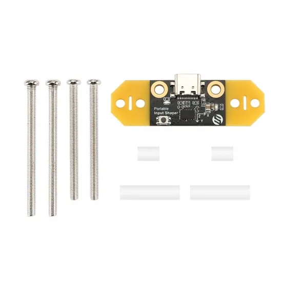
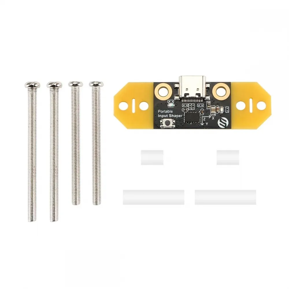
- 1 × FYSETC Portable Input Shaper.
- Mounting screws and spacers shown in the product image.
A data-capable USB-C cable is required to connect it to the host.
Pin configuration, mounting examples and files for other toolheads are available from the official FYSETC Portable Input Shaper repository. The current Klipper resonance-measurement guide should take precedence for the measurement workflow and up-to-date commands.