

- Stock: 48
- Model: CNC-Shield-V4
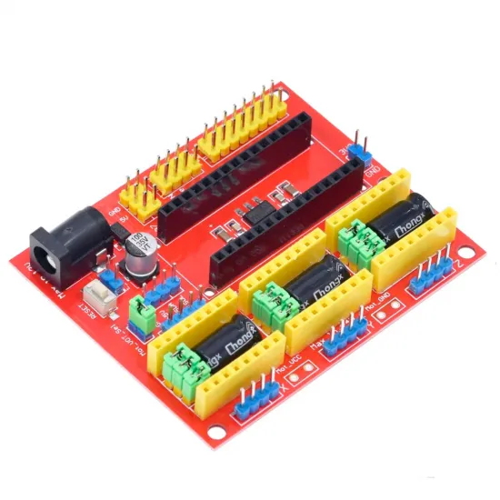
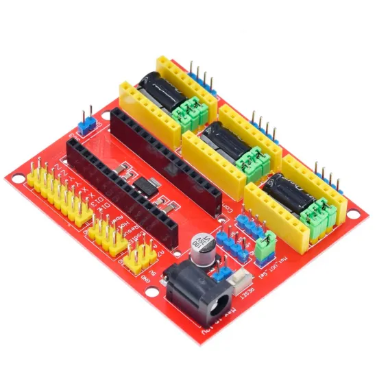
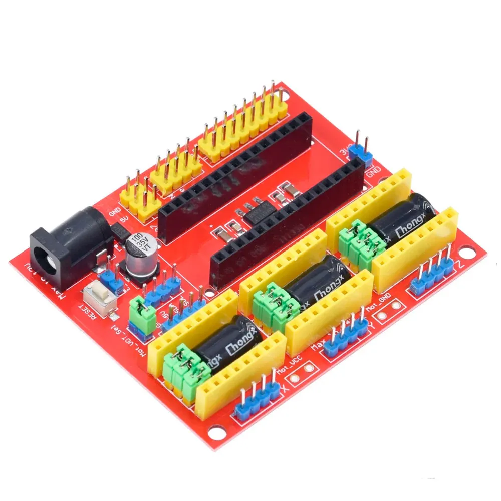
The CNC Shield V4 for Arduino Nano combines three stepper-motor channels on a compact board for CNC projects, laser engravers, plotters and positioning systems. It uses a classic 5 V ATmega328P-based Nano and provides three independent X, Y and Z sockets for compatible Pololu-format STEP/DIR drivers.
The board distributes signals, power and auxiliary connections, but it cannot operate on its own: an Arduino Nano, drivers, power supply, motors and firmware are required. Its main motion pin map matches GRBL, although an important D11/D12 detail must be resolved when installing limit switches or spindle/laser PWM control.
Main features
| Feature | Specification |
|---|---|
| Controller | Classic 5 V Arduino Nano with ATmega328P and compatible pinout |
| Axes | 3 independent channels: X, Y and Z |
| Drivers | 3 × 16-pin sockets for compatible Pololu-format STEP/DIR modules |
| Common models | A4988 and DRV8825, always subject to pinout and orientation checks |
| Motors | Four-wire bipolar motors; 3 × 2.54 mm-pitch connectors |
| Microstepping | 3 MS1/MS2/MS3 jumpers per axis |
| Normal power input | 7.5-12 V DC through barrel jack |
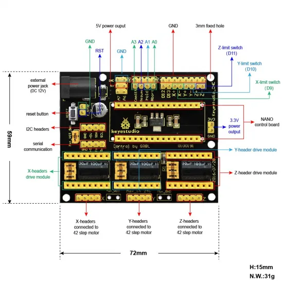
| Interfaces | Limit switches, GRBL controls, TTL serial, I2C, 5 V, 3.3 V, D12 and D13 |
| Nominal dimensions | 72 × 59 × 15 mm |
| Recommended firmware | GRBL for ATmega328P, configured for the actual wiring |
| Contents | 1 CNC Shield V4 with jumpers; remaining electronics and accessories not included |
Pin map
| Function | X | Y | Z |
|---|---|---|---|
| STEP | D2 | D3 | D4 |
| DIR | D5 | D6 | D7 |
| Limit input labelled on board | D9 | D10 | D11 |
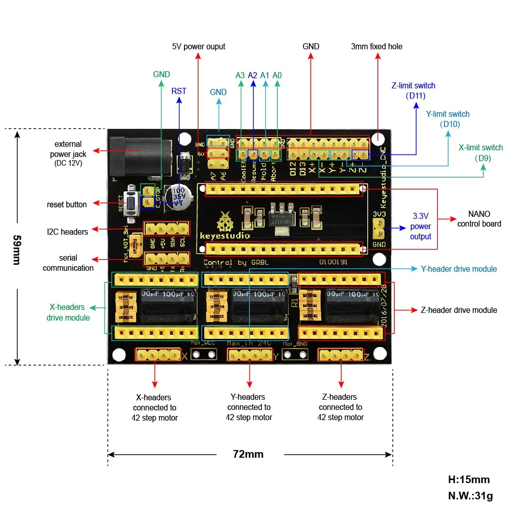
D8 enables all three drivers together. The auxiliary controls use the customary GRBL map: abort/reset on A0, hold on A1, resume/cycle start on A2 and coolant enable on A3. I2C uses A4/SDA and A5/SCL; standard GRBL also uses A5 for the probe input, so both functions cannot share that pin simultaneously without an adaptation.
The X+ and X- connectors share D9, just as Y+ and Y- share D10 and both Z connectors share the pin labelled D11. These are two physical connector positions per axis, not six independent inputs.
GRBL 1.1: resolving D11 and D12
VARIABLE_SPINDLE by default. In that configuration D11 is the spindle PWM output and the Z-limit input moves to D12, even though the board's Z connector is labelled D11. Do not wire the Z limit from the silkscreen alone.
Choose one of these two configurations:
- Keep PWM: use the default GRBL 1.1 configuration, connect the Z limit between the exposed D12 pin and GND, and use D11 as a logic-level PWM signal for the spindle or laser interface.
- Use the Z/D11 connector: disable
VARIABLE_SPINDLEinconfig.h, compile and flash GRBL. D11 returns to the Z-limit function and D12 becomes spindle enable, but standard variable PWM control is lost.
A custom pin-map build is also possible, but it must be prepared for the machine's required functions. Old firmware supplied with some kits may match D11, although installing an unknown version merely to avoid checking the pin map is not recommended.
A4988 and DRV8825 drivers
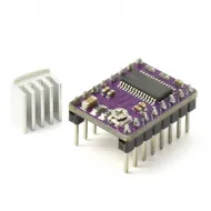
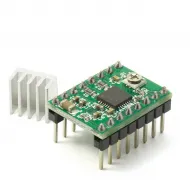
The board can be combined with the A4988 driver or DRV8825 driver. Before inserting a module, locate VMOT, GND and the logic signals on both the module and socket. PCB colour and potentiometer position are not reliable orientation references.
| MS1 | MS2 | MS3 | A4988 | DRV8825 |
|---|---|---|---|---|
| Open | Open | Open | Full step | Full step |
| Jumper | Open | Open | 1/2 | 1/2 |
| Open | Jumper | Open | 1/4 | 1/4 |
| Jumper | Jumper | Open | 1/8 | 1/8 |
| Jumper | Jumper | Jumper | 1/16 | 1/32 |
The DRV8825 provides additional combinations for 1/16 and 1/32 microstepping. Check the table for the actual module if those modes are required. The steps-per-millimetre values must be recalculated after changing the jumpers.
Current is adjusted independently on each driver according to the motor, the module's current-sense resistance and its cooling. There is no universal Vref value. Fit a heatsink and provide airflow when required, and never connect or disconnect motors or drivers while power is present.
Power
The normal configuration uses the 7.5 to 12 V DC barrel jack. This supply feeds the motor bus and the board's 5 V logic regulator. The Nano USB port is intended for programming and communication, not for powering the motors.
The board also provides Mot_VCC/Mot_GND pads, a motor-supply selector and a 24 V maximum marking. Using a motor voltage above 12 V is only suitable as an advanced configuration: the selector must isolate the motor bus, the Nano requires a separate logic supply, and continuity on the exact board revision must be checked before power-up. Never apply 24 V to the barrel jack, Nano VIN or the 5 V/3.3 V rails.
Nano outputs are logic signals. A spindle, laser, pump or extraction system requires a compatible power interface, MOSFET, relay or controller; it must never be powered directly from D11, D12, D13 or A3.
Recommended commissioning procedure
- Confirm that the Nano is a 5 V ATmega328P model and insert it in the correct orientation.
- Flash GRBL before installing the drivers and decide whether PWM or the Z/D11 connector will be used.
- With all power removed, set the microstep jumpers and verify each driver's orientation.
- Identify both coils in each motor and connect them as pairs; do not test combinations on a powered board.
- Set driver current limits before demanding torque or speed.
- Test one axis at a time at low speed, confirm direction and travel, and then connect limits, spindle or laser.
- Configure X/Y/Z steps per millimetre with
$100-$102, rates with$110-$112, accelerations with$120-$122and travels with$130-$132for the actual mechanics. - Verify homing and limits at low speed before running a complete G-code file.
Applications and limitations
It is suitable for small three-axis CNC routers or engravers, plotters, XY tables, positioning systems and custom laser projects. Compatibility with a specific machine depends on its motors, drivers, voltage, limit switches, travel, tool interface and GRBL configuration.
This is not a complete 3D-printer mainboard: it does not provide dedicated thermistor inputs, protected heater outputs or thermal monitoring. For Arduino UNO projects, the CNC Shield V3 for Arduino UNO R3 is an alternative; the two shields use different formats and connections and are not direct replacements.
It is for you if...
- You want to control three STEP/DIR axes with a classic Arduino Nano and GRBL.
- Your project uses bipolar motors suitable for an A4988, DRV8825 or another verified-pinout driver.
- You can configure firmware, current, microstepping, limits and mechanical parameters.
It is not for you if...
- You need four independent axes, differential external drivers or high currents.
- You need a complete controller for 3D-printer heaters and temperature sensors.
- You want to connect a power spindle or laser directly without a suitable interface.
- Your controller is a Nano Every, Nano 33, ESP32, UNO, Mega or another board with a different pinout or logic level.