

- Stock: 2
- Model: MELLOW-GOLIATH-AIR-V2

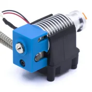
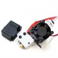
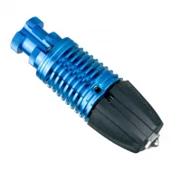
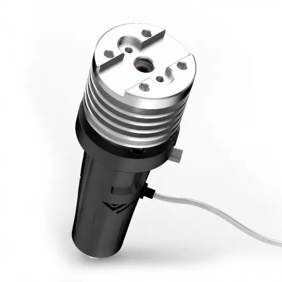
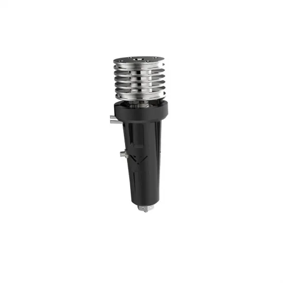
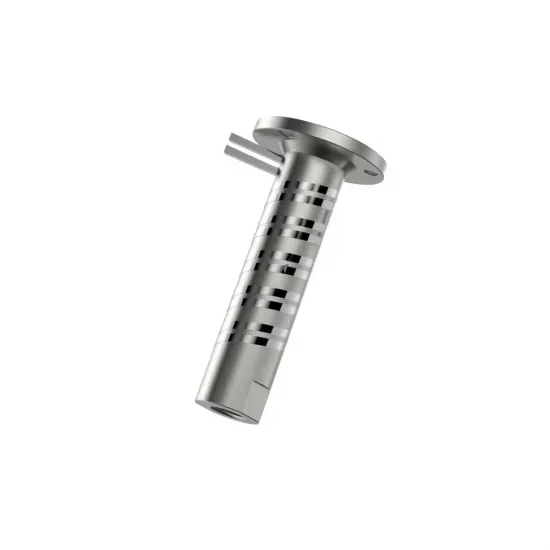
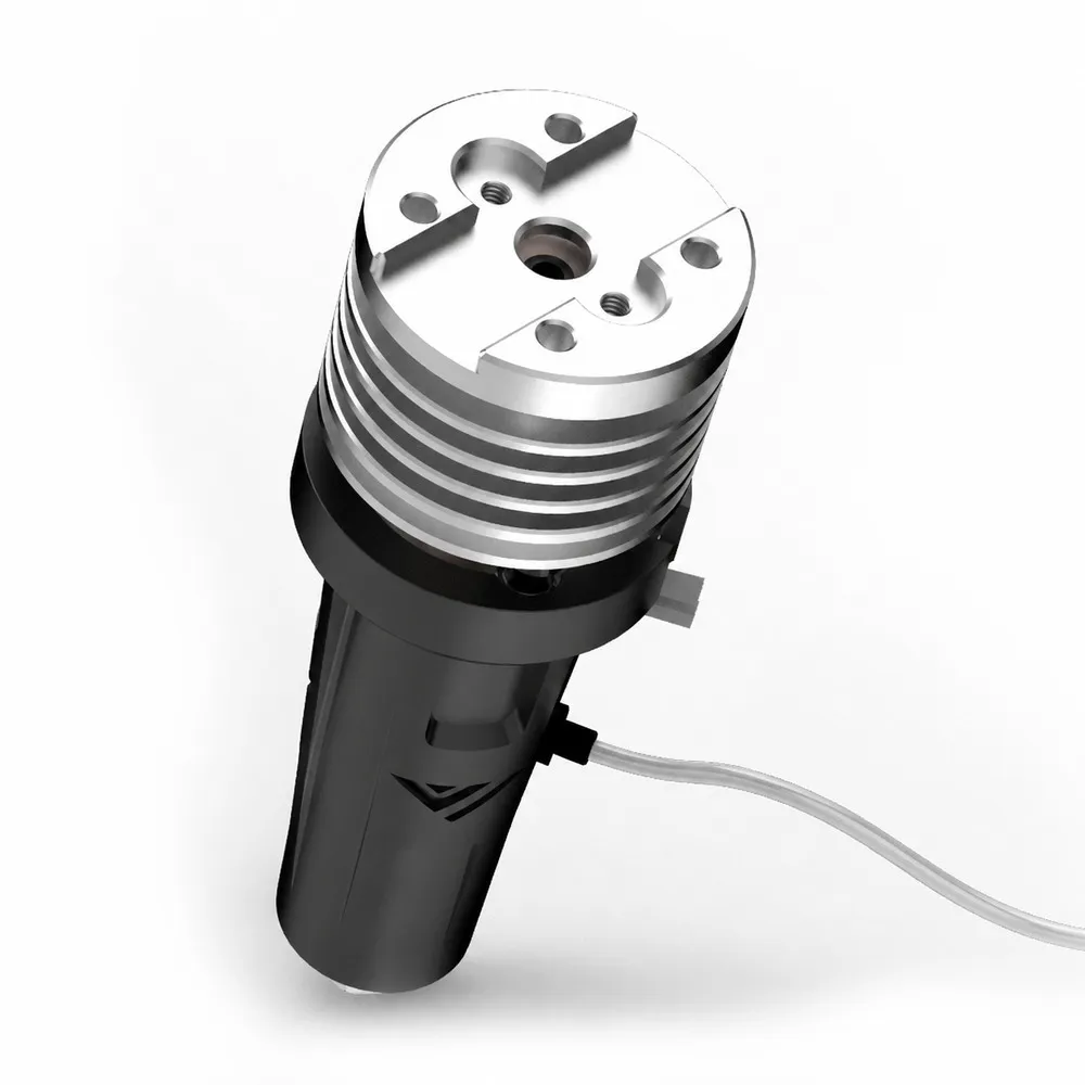
The Mellow Goliath AIR V2 is a high-flow hotend developed by the VzBoT team and manufactured by Mellow for 3D printers that need to melt a substantial volume of filament consistently. It combines a long nickel-plated copper heater block, distributed 100 W heating at 24 V and a copper/zirconia heatbreak, designed to feed well-melted material to the nozzle as print speed, line width or layer height increases.
This is the air-cooled version, supplied with a 0.4 mm plated copper V6 nozzle, an M3 threaded PT1000 sensor and a silicone sock. The heatsink fan and fan duct are not included and must be added to complete the installation.
What makes the Goliath design different?
A long hot zone with distributed heating
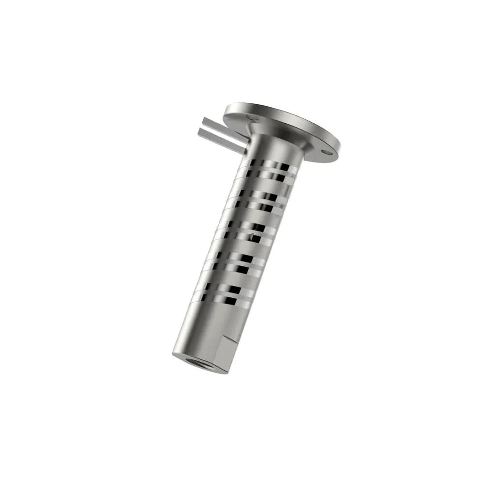
Rather than concentrating heat in a small block with a conventional heater cartridge, the Goliath uses a nichrome wire heating element arranged around the block. Copper helps distribute the heat, while the elongated geometry gives the filament a longer path through the hot zone. This combination is particularly useful when a conventional hotend becomes the limiting factor for extrusion flow.
The 100 W rating provides power headroom to recover temperature during extrusion. It is not a print-speed rating: performance also depends on the polymer, temperature, nozzle, extruder force and part cooling. Setting a suitable volumetric flow limit helps make use of the design without relying on excessive temperature to compensate for incomplete melting.
Nickel-plated copper and zirconia thermal isolation
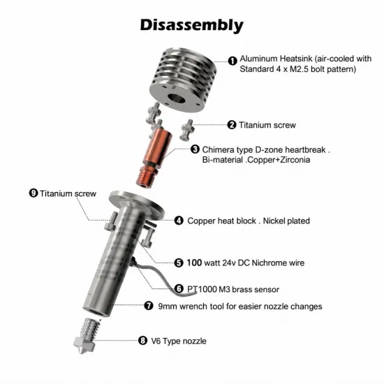
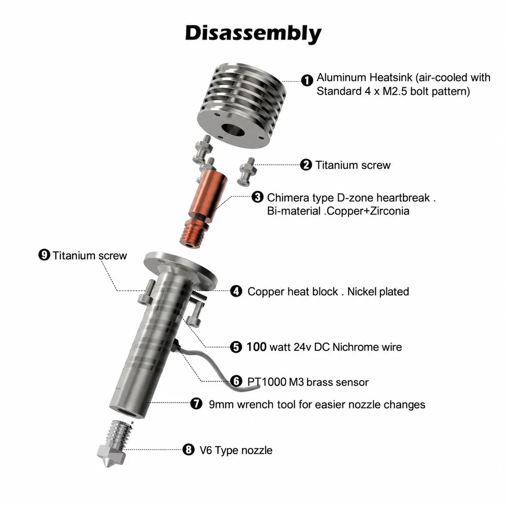
The nickel-plated copper block combines copper's thermal conductivity with a protective finish. The heatbreak uses copper and zirconia, a ceramic that limits heat transfer towards the cold zone. The aluminium heatsink removes the heat that reaches this area with help from its fan.
Separating melting from filament feeding helps keep the filament controlled before it enters the hot zone. However, zirconia requires careful handling: avoid bending the heatbreak, pulling it forcefully or using it to resist nozzle-tightening torque. The titanium support elements are part of the assembly's structure, but do not replace holding the heater block with a wrench during maintenance.
V6 nozzle and M3 PT1000 included
The 0.4 mm plated copper nozzle is a versatile starting point for detailed parts and general printing, with good thermal conductivity. The V6 format allows you to select other nozzle diameters or materials for the job. For abrasive filaments, choose a nozzle with a stated wear-resistant specification; a coating on a copper nozzle does not, by itself, make it equivalent to a hardened nozzle.
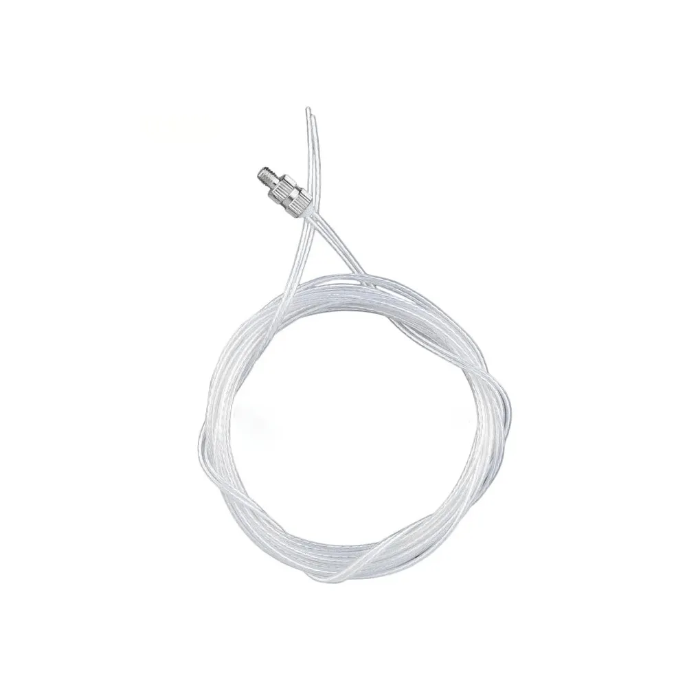
The PT1000 is a platinum resistance sensor, not a 100 kΩ NTC thermistor. Its M3 threaded mounting fits into the side of the block. Both the electronics input and the firmware must be configured for PT1000: merely changing a sensor label in the printer profile does not change its circuit or temperature conversion.
Technical specifications
| Specification | Goliath AIR V2 |
|---|---|
| Filament | 1.75 mm. |
| Heater supply | 24 V DC, 100 W nominal; approximately 4.17 A at nominal power. |
| Heating system | Nichrome wire distributed around the block. Not a conventional 6 mm cylindrical heater cartridge. |
| Block / heatbreak / heatsink | Nickel-plated copper / copper and zirconia / aluminium. |
| Included sensor | PT1000 with M3 threaded mounting. |
| Included nozzle | V6 type, M6 thread, plated copper, 0.4 mm orifice. |
| Cooling | Air cooling, requiring a separate fan and duct, not included. |
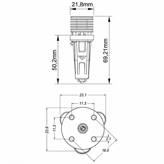
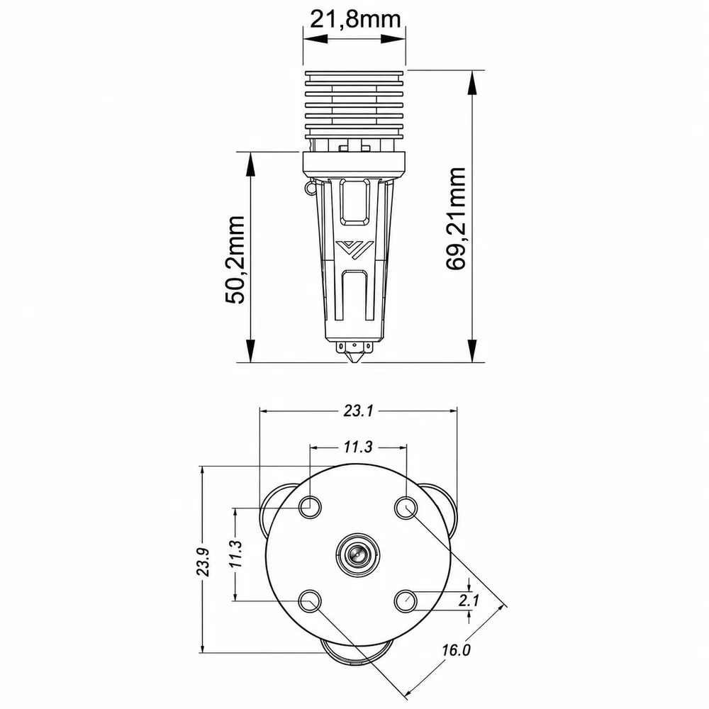
| Reference height | 69.21 mm according to the manufacturer's AIR drawing. |
| Reference dimensions | Heatsink: 21.8 mm dimension in side view. Upper plan-view envelope: 23.1 × 23.9 mm. Illustrated lower section: 50.2 mm; this is an external dimension, not the internal melt-zone length. Allow additional room for wiring, fan and duct. |
| Top mounting | Four M2.5 screws, with an 11.3 × 11.3 mm centre-to-centre pattern and a 16.0 mm reference diagonal according to the drawing. |
| Standard sock | Silicone, limited to 300 °C. Working temperature must also respect the limits of the rest of the installation. |
Compatibility and mounting
The Goliath originates in the VzBoT ecosystem, with printhead and duct designs for its installations. It is a particularly suitable option for VzBoT 235 and VzBoT 330 projects with a Goliath AIR mount. Choose the duct intended for your printed or CNC printhead, not simply one that accepts the same fan size.
It can also be integrated into projects such as Voron 2.4, Voron Trident or HevORT using an adapted, verified mount. It is not a universal drop-in replacement: check the mounting pattern, nozzle-tip height, position relative to the extruder, available Z travel, probe and cooling ducts. Sharing a four-screw pattern with another hotend does not guarantee that the rest of the printhead fits.
A V6 nozzle does not mean a V6 hotend mount. The Goliath uses M6 V6 nozzles, but its upper mounting is not the groove-mount clamp of a classic V6. It is also different from the Goliath WATER version, which requires a liquid-cooling system.
The VzBoT guide recommends a 2510 fan and a Goliath AIR duct. Consider the 24 V GDSTIME 2510 fan if its voltage, airflow and mounting suit your installation. This fan keeps the heatsink cool and is separate from the fan that cools the printed part. It must run when required by hotend temperature, rather than depending on the slicer's part-cooling command.
Electrical installation: 100 W heater and PT1000 sensor
Connect the heater to a 24 V hotend output with sufficient load capacity and headroom: 100 W nominal corresponds to approximately 4.17 A. Check the output's continuous rating, connector, terminals, wiring, protection and power supply. A nominal 5 A limit does not mean that any cable or installation can sustain this load without reviewing its thermal conditions.
The sensor connects to a temperature input, never to the heater output. It can be read by a PT1000-compatible analogue input or a dedicated RTD circuit such as MAX31865, provided its wiring and reference resistance are configured for PT1000. An input designed for a different sensor must not be assumed suitable without checking the board.
The Mellow FLY SHT36 V3 Plus includes MAX31865 and can be an option for a Klipper toolhead installation. Check its heater-output limit, power supply, connectors and specific configuration before combining the products. Sensor compatibility and heater-output capacity are two separate checks.
PT1000 configuration in Marlin, Klipper and RepRapFirmware
The following settings apply to direct PT1000 measurement through an analogue input. The stated pull-up resistance must match the resistor physically fitted to the board; changing a firmware value does not change that resistor. Do not apply these examples to a MAX31865, which requires its own configuration.
| Firmware | Setting and condition |
|---|---|
| Marlin | PT1000: TEMP_SENSOR_0 1047 for a 4.7 kΩ pull-up; 1022 for 2.2 kΩ; 1010 for 1 kΩ. Confirm that the installed Marlin version includes the selected table. |
| Klipper | In the existing extruder section: sensor_type: PT1000. Set pullup_resistor to the physical resistance: 4700, 2200 or 1000 Ω, as appropriate for the board. Keep the actual sensor_pin. |
| RepRapFirmware 3 | Create or adjust the sensor with M308 and Y"pt1000". The sensor number, pin and R parameter, if used, must match the hardware and existing configuration. |
Marlin example for the first hotend, only with a physical 4.7 kΩ pull-up:
#define TEMP_SENSOR_0 1047Klipper sensor-parameter example, only for an analogue input with a 4.7 kΩ pull-up; add these to the existing extruder section:
sensor_type: PT1000
pullup_resistor: 4700
RepRapFirmware 3 example only if the sensor is S1, connected to the pin named temp1, with a 4.7 kΩ pull-up:
M308 S1 P"temp1" Y"pt1000" R4700In RepRapFirmware, associate this sensor with the correct heater using M950, with suitable temperature limits configured. In all three systems, check that the room-temperature reading is plausible before switching on the heater. Keep thermal protections active and recalibrate temperature control after the change; do not reuse the previous hotend's PID values without checking them.
Setting up for high-flow printing
- Check the cold installation: mounting, nozzle, sensor, heatsink fan, insulation, terminals and the printhead's full travel. Wiring must not rub against the hot zone.
- Verify the sensor and heat progressively: check that temperature rises sensibly, thermal protections work and the heatsink receives cooling.
- Calibrate temperature control: use the firmware's tuning function—PID in Marlin/Klipper or heater-model autotuning in RepRapFirmware—at a suitable working temperature, with the sock and cooling in their actual operating conditions.
- Readjust geometry: check Z offset, nozzle-to-probe relationship and travel limits. Changing hotend height can affect the first layer and usable travel.
- Measure flow for the material: increase demand gradually and use a volumetric limit with headroom below the point where print quality deteriorates, under-extrusion appears or feeding fails.
- Adjust retraction and pressure compensation: the hot zone differs from the previous hotend. Check retraction, Klipper Pressure Advance or Marlin Linear Advance with the actual filament and extruder.
A useful approximation for hotend demand is flow = line width × layer height × speed. A 0.45 mm line, 0.20 mm layer and 200 mm/s speed require approximately 18 mm³/s. At the same speed, a 0.80 mm line and 0.30 mm layer require approximately 48 mm³/s. These are demand examples, not guaranteed Goliath performance: a speed stated in mm/s alone cannot compare melting capacity.
Temperature and maintenance
The included silicone sock is limited to 300 °C. Do not exceed this temperature with the sock fitted, or raise firmware limits without reviewing the sensor, its wiring, connections and other components. Higher-temperature operation requires a specific assessment of the complete installation and appropriate insulation; removing the sock alone is not sufficient.
Use suitable tools to change the nozzle and work with the hotend heated, within its operating limits. The Goliath guide specifies a 1.2–1.4 N·m nozzle-tightening torque. Hold the block using its 9 mm wrench flats so the load does not pass through the zirconia heatbreak or printhead mount. Avoid overtightening or changing the nozzle cold, and protect yourself against burns.
Tighten the M3 PT1000 gently: it does not require nozzle-level torque. Heater leads can be carefully oriented, but must not be bent repeatedly or subjected to pulling as the printhead moves. Keep the hot zone away from plastics and wiring, with strain relief outside it. If heatbreak removal is necessary, follow the specific service procedure and do not pull on the ceramic section.
Included items and replacement parts
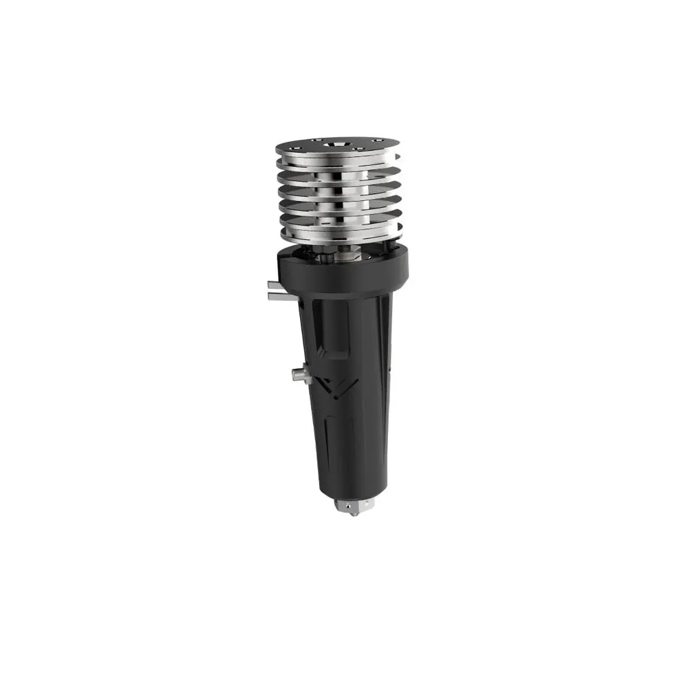
- Mellow Goliath AIR V2 hotend with air-cooled heatsink, copper/zirconia heatbreak and 100 W, 24 V heater block.
- 0.4 mm plated copper V6 nozzle.
- M3 threaded PT1000 sensor.
- Silicone sock.
Fan and cooling duct are not included. Check replacement compatibility component by component: the nozzle uses the V6 format, whereas the block, heatbreak, sock and threaded sensor must match the Goliath design. A 3 mm cylindrical PT1000 capsule is not a mechanical replacement for the M3 PT1000 just because it has the same electrical sensor type.
For a replacement nozzle, consider the 0.4 mm plated copper V6 nozzle for 1.75 mm filament, respecting the seating geometry and installation procedure. When selecting a nozzle in a different material, check thread length, sealing geometry and operating temperature, and readjust the printing profile where needed.
It is for you if...
- You are building or upgrading a high-performance printer and need melting capacity for wide lines, thick layers or high print speeds.
- Your VzBoT or adapted printhead has the mounting and space required for Goliath AIR.
- You want V6 nozzles and a PT1000 sensor, and can correctly configure cooling, electronics and firmware.
It is not for you if...
- You need a replacement that fits a V6 groove mount or a printhead designed for a different hotend without adaptation.
- You need the water-cooled version or a kit that already includes a fan and duct.
- Your printer lacks a 24 V installation capable of supplying the 100 W heater with headroom.
- You intend to exceed 300 °C with the included sock without preparing and verifying a specific installation.
Assembly documentation
The VzBoT Goliath assembly guide provides further installation and maintenance procedures. The Goliath repository contains ducts for 2510 fans and printhead variants. Select files for the AIR version and your specific mount, respecting their licence conditions.