


This offer ends in:
- Stock: 57
- Model: HotendV6-HQ

Model:

Classic V6

V6 encapsulated thermitor

Compact V6 TOP components
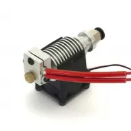
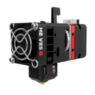
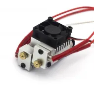
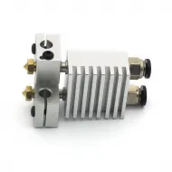
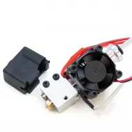
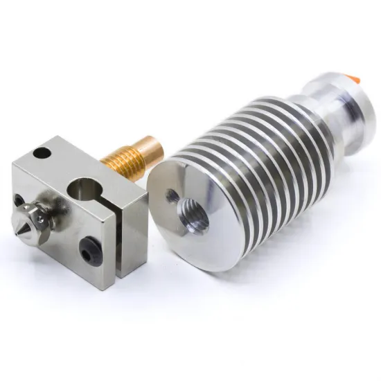
Compact V6 hotend for 1.75 mm filament, configured and assembled by HTA3D with your selected components. Choose the heatbreak, heater block, nozzle, heater cartridge, thermistor connector and PTFE length to suit the material, power system and printer installation.
This is not a fixed configuration and it is not necessarily all-metal: its final behaviour depends on the selected options. The assembly is supplied built to simplify installation, but it still needs to be checked, adjusted and calibrated on the destination machine.
Configure the hotend for your project
| Component | Options | Selection guide |
|---|---|---|
| Heater cartridge | 12 V 40 W, 12 V 50 W, 24 V 40 W or 24 V 50 W | Voltage must match the PSU; board, MOSFET, connectors and wiring must support the power |
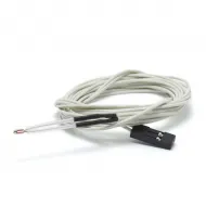
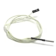
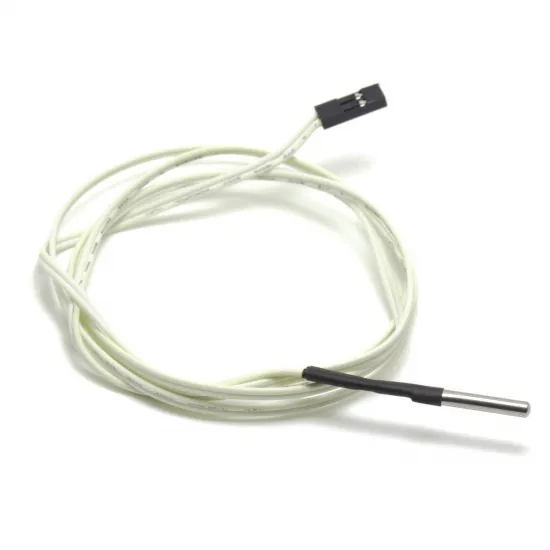
| Thermistor and connector | 3 mm encapsulated NTC 100K Beta 3950; Dupont or XH2.54 | Choose the correct physical connector and verify the board pinout; the sensor curve does not change |
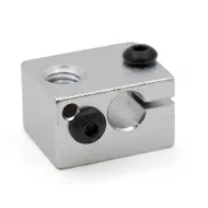
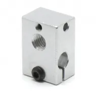
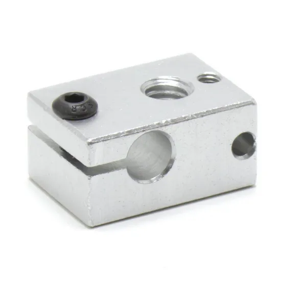
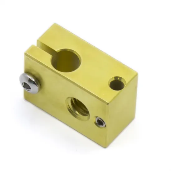
| Heater block | Aluminium or brass, M6 nozzle thread and 3 mm sensor bore | Aluminium prioritises low weight and response; brass provides greater mass and thermal inertia |
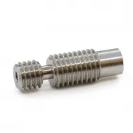
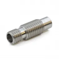
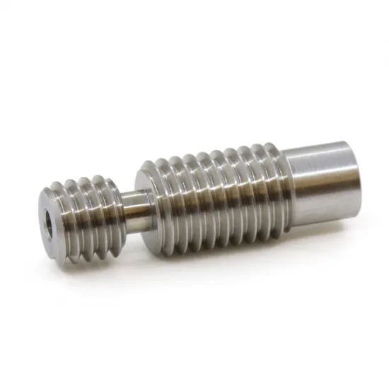
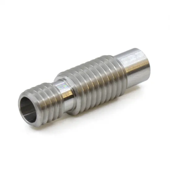
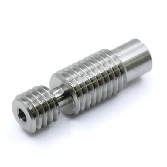
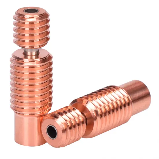
| Heatbreak | All-metal stainless steel, PTFE-lined stainless steel, all-metal titanium or bimetal | Select according to material, temperature, cooling and maintenance requirements |
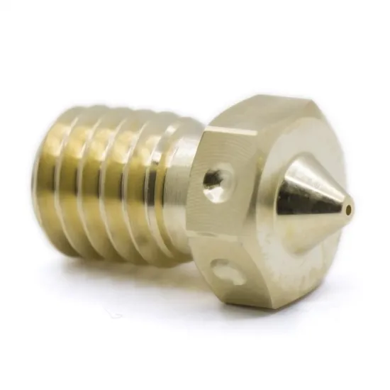
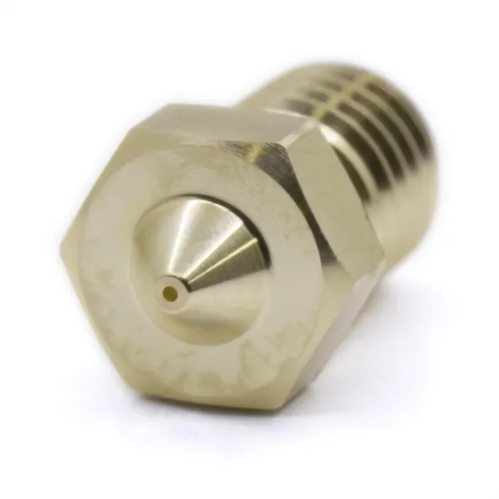
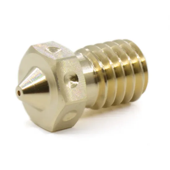
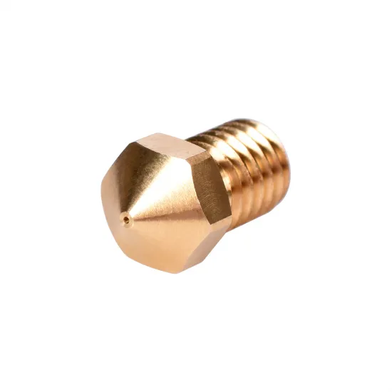
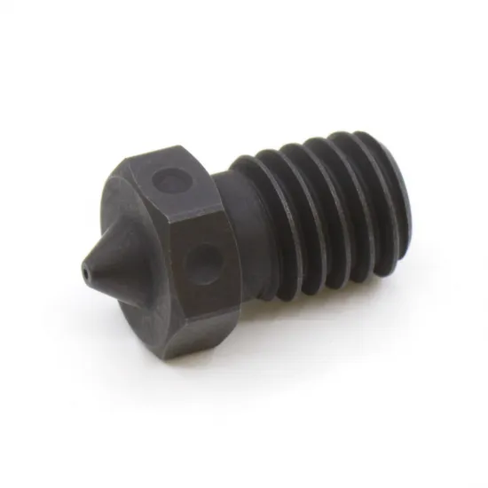
| V6 nozzle | 0.35, 0.4 or 0.5 mm brass; 0.4 mm brass T-V6; 0.4 mm hardened A2 steel | Balance detail, productivity, thermal conductivity and abrasion resistance |
| PTFE tube | To the heatsink, 30 cm, 70 cm or 1 m | Depends on extruder position and the actual filament path |
Choosing the heatbreak
- PTFE-lined stainless steel: provides easy filament guidance for common materials. The tube approaches the hot zone, so its temperature limit must be respected and it should be treated as a service item.
- All-metal stainless steel: removes PTFE from the hot zone. It requires continuous cooling and usually shorter, recalibrated retraction.
- All-metal titanium: aims to reduce heat transfer towards the heatsink; correct cooling and tuning are still required.
- Bimetal: combines materials to provide a more defined thermal transition. It is an interesting choice for demanding setups, but does not guarantee more flow or eliminate clogs by itself.
Heater block and nozzle
The aluminium block is lighter and responds quickly to power changes. The brass block adds thermal mass, which can help hold temperature as material demand changes, at the cost of extra weight and a slower response.
For general use, 0.4 mm provides the familiar balance between detail and output. The 0.35 mm nozzle prioritises fine features, while 0.5 mm allows wider lines and greater potential productivity. The hardened A2 steel option is intended for abrasive filaments, although its lower thermal conductivity than brass may require temperature, speed or flow adjustments.
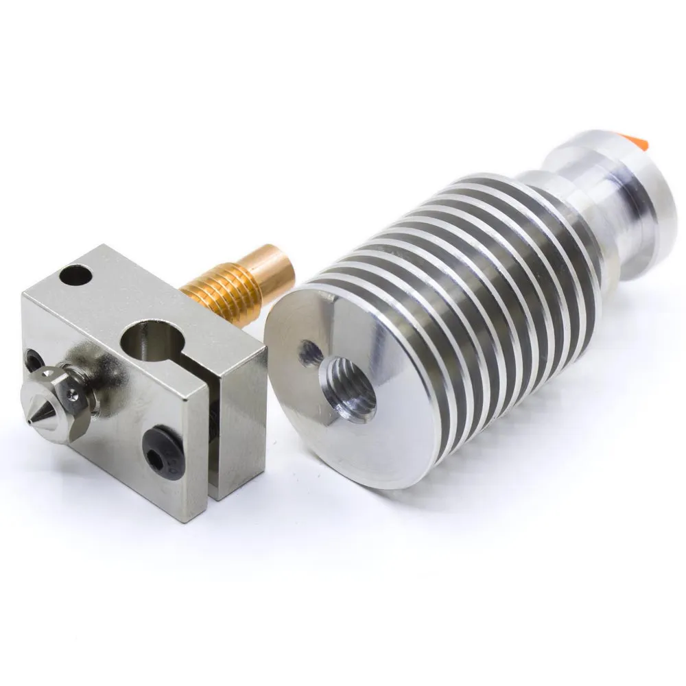
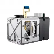
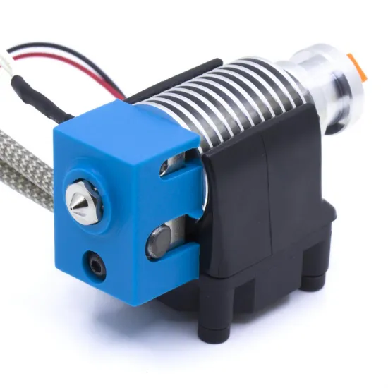
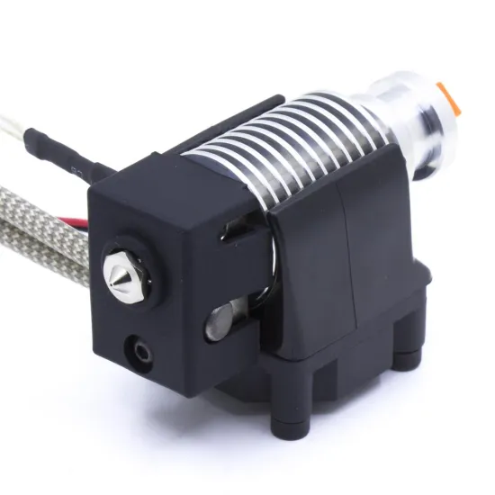
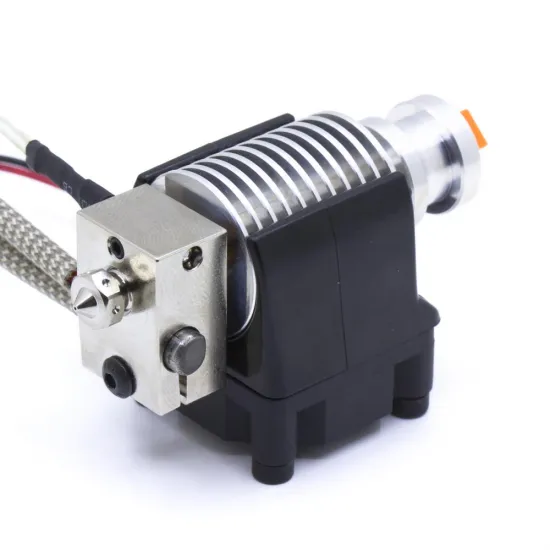
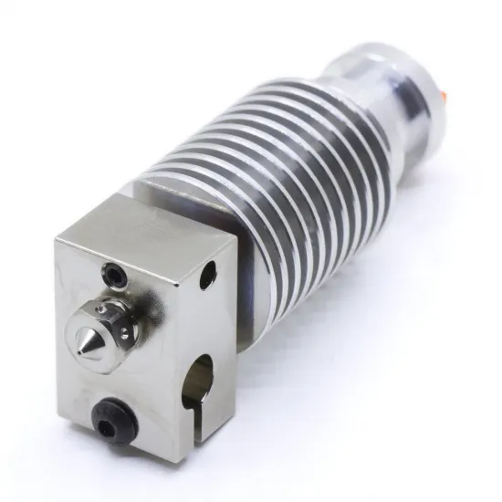
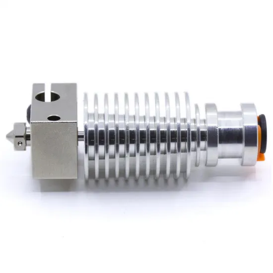
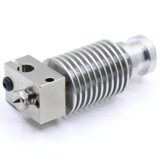
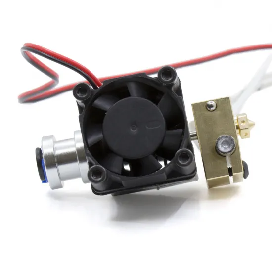
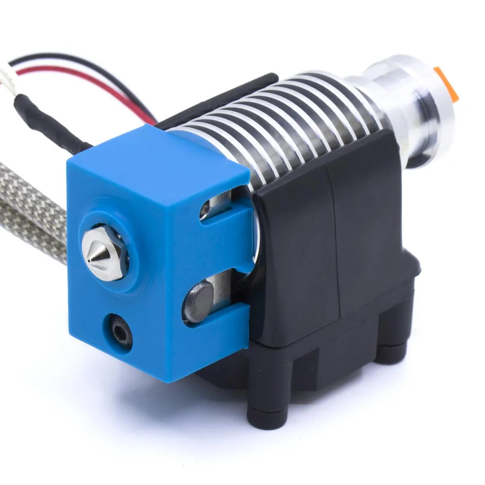
Photographs show example configurations. Sock colour and the exact block, heatbreak, nozzle, heater, connector and PTFE supplied may vary with the selected options.
Mechanical and electrical compatibility
The heatsink uses a V6-type upper interface or Groove Mount, but this does not make the hotend a direct replacement for every printer described as V6-compatible. Check the mount, overall and nozzle-tip position, part-cooling duct, probe, extruder, fittings and available space. The Z offset must be checked after installation.
A Dupont or XH2.54 connector does not establish controller-board compatibility by itself. Pitch, housing, pinout and input type must all match. The thermistor itself is not polarised, but an incorrect pin assignment may prevent measurement or create an unsafe connection.
| Heater | Calculated nominal current | Ideal nominal resistance |
|---|---|---|
| 12 V 40 W | 3.33 A | 3.60 Ω |
| 12 V 50 W | 4.17 A | 2.88 Ω |
| 24 V 40 W | 1.67 A | 14.40 Ω |
| 24 V 50 W | 2.08 A | 11.52 Ω |
These are nominal calculations using I=P/V and R=V²/P, not measurements or guaranteed tolerances. Verify the supplied variant with power disconnected. Connecting a 12 V heater to 24 V can produce dangerously excessive power, while a 24 V heater on 12 V will heat far less than intended.
Installation and commissioning
- Before connection, check voltage, power, approximate resistance, connectors and every cable route.
- Check that the heater and sensor are fully inserted and retained. Do not overtighten the sensor.
- The nozzle must seal against the heatbreak rather than the heater-block face. A small gap should remain between the nozzle hex and block before final tightening.
- Perform the final hot tightening while holding the block with a suitable tool. Do not use the heatsink as a lever or twist the wiring, and remain below the lowest temperature limit in the chosen configuration.
- Verify that the heatsink fan runs continuously whenever the hotend is hot.
- Recalibrate Z offset, temperature, retraction, flow, pressure/linear advance and thermal control before printing.
Thermistor and heater configuration
The included sensor is a 3 mm encapsulated NTC 100K Beta 3950 thermistor. Dupont and XH2.54 only change its physical connection.
- Marlin: on the common 4.7 kΩ pull-up input use
#define TEMP_SENSOR_0 11and keep thermal protection enabled. After installation, an adaptable PID example isM303 E0 C8 S210 U1, followed byM500. If the build uses MPC, follow theM306 Tprocedure. - Klipper: use
sensor_type: Generic 3950and reviewsensor_pin,heater_pin,min_temp,max_temp,max_powerandnozzle_diameter. Tune withPID_CALIBRATE HEATER=extruder TARGET=210and finish withSAVE_CONFIG. - RepRapFirmware: use
M308to define a 100 kΩ Beta 3950 thermistor on the actual input, andM950for the output. Tune the real tool or heater withM303, inspect it withM307and save where appropriate. Pins and tool numbers depend on the board.
Command temperatures are examples and must be adapted to a safe, representative use case. Before heating to print temperature, confirm a plausible ambient reading, observe a progressive rise and verify that thermal protections respond correctly. Select the actual replacement sensor curve if the thermistor is changed.
Package contents
- Compact aluminium V6 heatsink with filament-guide fitting.
- 3010 heatsink cooling fan and mount.
- Heatbreak, heater block, nozzle, heater cartridge and thermistor according to the selected options.
- Selected thermistor connector and PTFE-tube length.
- Suitable silicone sock for the fitted block where included with the supplied configuration.
It is for you if
- You want a compact V6 hotend assembled with components selected for your project.
- You need to choose between 12 or 24 V, 40 or 50 W, several heatbreaks and different nozzles.
- You can verify the mechanical, electrical and firmware integration and complete the final calibration.
It is not for you if
- You need a drop-in replacement without checking mount, height, probe, cooling, voltage, connectors and firmware.
- You require one certified maximum temperature for every possible combination.
- You plan continuous abrasive-filament use but have selected a brass nozzle.
Spares and maintenance
Separate replacements include the aluminium V6 block for 3 mm sensors, brass V6 block for 3 mm sensors, encapsulated B3950 thermistors with either a Dupont connector or XH2.54 connector, the 0.4 mm hardened A2 steel V6 nozzle and the V6 silicone sock. The hotend maintenance spanner can be used to hold the block during a nozzle change.