

- Stock: 55
- Model: 17HS2408
Model:

17HS2408

17HS3401

17HS4401

17HS4401s-09

17HS8401

17hs8401S-09

17HS6401

17HS6401s-09
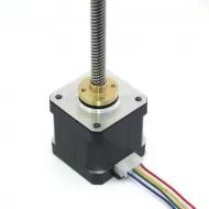
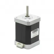
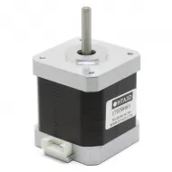
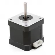
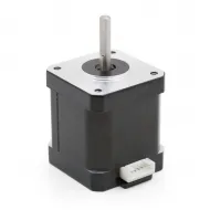
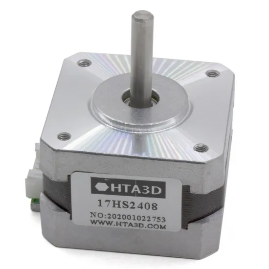
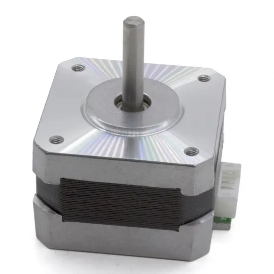
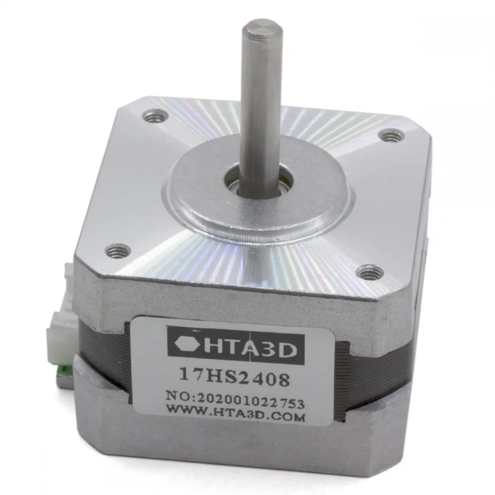
The 17HS2408 is an especially compact bipolar NEMA 17 stepper motor. It combines a 28 mm body, a round 5 mm shaft and an approximate weight of only 150 g. Its reduced size and inertia suit light mechanisms, feeders, small axes and projects where space or moving mass matter more than the torque of a longer NEMA 17 motor.
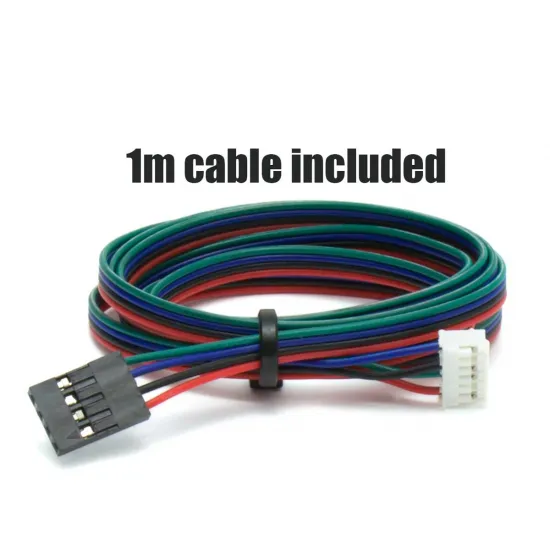
It provides 12 N·cm holding torque, a 1.8° step angle and a rated current of 0.6 A per phase. A 1 m cable is included with the controller-side termination selected in the product options.
Technical specifications
| Feature | Value |
|---|---|
| Model | 17HS2408 / 42HS28 format |
| Type | 2-phase, 4-wire bipolar hybrid stepper motor |
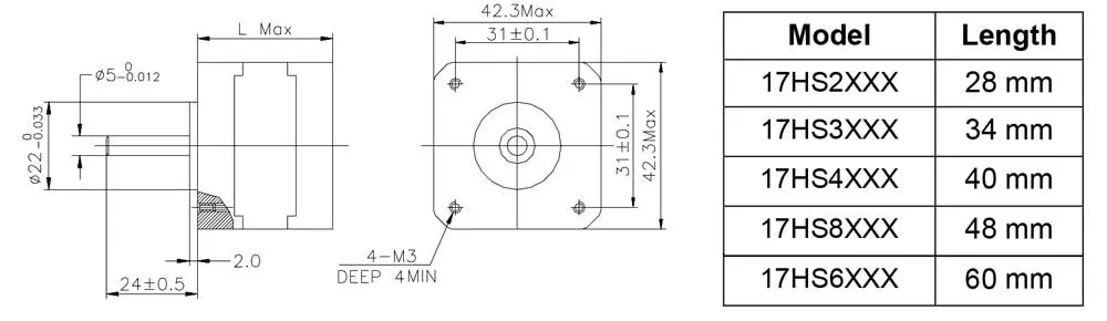
| Frame | NEMA 17, 42.3 mm maximum face size |
| Step angle | 1.8°; 200 full steps per revolution |
| Rated current | 0.6 A per phase |
| Phase resistance | 8 Ω per phase |
| Phase inductance | 10 mH per phase |
| Minimum holding torque | 12 N·cm = 0.12 N·m ≈ 1.22 kgf·cm |
| Maximum detent torque | 1.6 N·cm |
| Rotor inertia | 34 g·cm² |
| Body | 28 mm long |
| Shaft | Round, Ø5 mm; 24 ± 0.5 mm projection |
| Mounting | 4 M3 threaded holes; 31 ± 0.1 mm centres |
| Pilot | Nominal Ø22 mm |
| Weight | Approximately 150 g |
| Included cable | 1 m; controller termination according to the selected option |
A short NEMA 17 for moderate loads
Its main advantage is its compact size. The 28 mm body is lighter and shorter than 40 or 48 mm NEMA 17 versions, but it also develops less torque. Choose it when the mechanism requires no more than 12 N·cm holding torque and sufficient margin has been allowed for acceleration, friction and transmission losses.
Holding torque is measured while the powered motor is stationary; it is not the torque available at every speed. Usable torque decreases as speed rises and also depends on the driver, supply voltage, current setting, acceleration and load inertia.
Where a project needs more margin while retaining a NEMA 17 mounting face, consider the 17HS4401 NEMA 17 motor with 40 N·cm torque. It is not an automatic replacement: its body is longer, it requires more current and it changes assembly mass.
Check before installation
- NEMA 17 face, 31 mm mounting pattern and clearance for the 28 mm body.
- Round 5 mm shaft, usable length and pulley, gear or coupling attachment.
- Required dynamic torque, not only the torque needed to hold a stationary load.
- A compatible bipolar driver that can limit current correctly.
- Coil pairs and controller or driver pin order.
- The selected cable termination; a connector physically fitting does not prove that its pinout is correct.
NEMA 17 mainly defines the front mechanical interface, not complete compatibility. Two NEMA 17 motors may have different body lengths, shafts, torque, current, inductance, connectors and electrical pin orders.
Current, driver and supply voltage
The rated current is 0.6 A per phase. This does not mean a 1.2 A driver setting and should not be copied blindly: some drivers specify RMS current, some peak current and others are adjusted through VREF. Follow the driver procedure and begin conservatively.
At 0.6 A and 8 Ω, the nominal resistive voltage drop is approximately 4.8 V per winding. This does not make it a fixed 4.8 V supply motor. 3D printers and CNC machines normally use a current-regulated chopper driver that can operate from a higher supply voltage within the limits of both controller and driver.
Too little current reduces available torque; excessive current increases motor and driver temperature. Start with conservative current, speed and acceleration, then increase only after checking motion, temperature and missed steps.
Finding coil pairs and setting direction
- Switch off and unplug the equipment completely.
- Use a multimeter in resistance or continuity mode to identify the two wires forming each coil.
- Connect one pair to one driver phase and the other pair to the second phase according to the controller documentation.
- If direction is reversed, swap both wires of one coil or invert direction in firmware where appropriate.
Do not rely only on wire colours. Never connect or disconnect the motor while the driver is powered, as winding energy can create damaging voltage spikes.
Marlin, Klipper and RepRapFirmware setup
This motor provides 200 full steps per revolution. Linear calibration depends on microstepping and transmission:
steps/mm = (200 × microsteps × reduction ratio) / travel per output revolution
- For a directly driven GT2 pulley, travel per revolution is tooth count multiplied by 2 mm.
- For a leadscrew, use its actual lead in mm/revolution, which is not always the same as thread pitch.
- For gearing, include the ratio between motor turns and output turns.
- Marlin: set the calculated value with
M92 X...,Y...,Z...orE.... UseM500only when EEPROM is enabled and the change should be stored. - Klipper: set
full_steps_per_rotation: 200, actual microstepping and arotation_distanceequal to travel per revolution. Addgear_ratiowhen a reduction is present. - RepRapFirmware: use
M350for microstepping andM92for steps per unit. Current throughM906only applies to firmware-controlled drivers.
Microstepping improves smoothness and command resolution, but it does not proportionally multiply mechanical accuracy or usable torque. Measure actual travel and correct the final value on the assembled machine.
Installation and first test
- Make sure the bracket does not distort the motor face and that M3 screws do not bottom out.
- Align the pulley, gear or coupling without side-loading the shaft.
- Verify coil pairs and pinout before applying power.
- Run short movements at low speed and acceleration.
- Check direction, noise, temperature and missed steps.
- Test progressively with the real load before considering the machine calibrated.
For a standalone installation, the NEMA 17 L-shaped mounting bracket may be used after checking clearance, cable orientation and transmission alignment.
Package contents
- 1 NEMA 17 17HS2408 stepper motor.
- 1 m cable with the selected controller-side termination.