

- Stock: 74
- Model: dual-axis-module
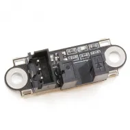
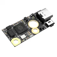
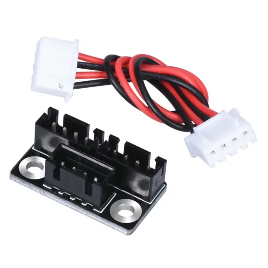
This parallel stepper motor splitter module connects two four-wire bipolar motors to a single controller-board motor output. It is commonly used on 3D printers with two Z-axis motors, although it can also serve other axes or mechanisms where two motors must move simultaneously from the same driver.
It is a passive splitter: it does not contain a second controller or generate independent signals. Both motors receive the same steps, direction and current from one driver, so they must be electrically compatible and operate within a suitable mechanical system.
Main specifications
| Feature | Value |
|---|---|
| Function | Split one stepper-motor output between two parallel motors |
| Motor type | 4-wire bipolar |
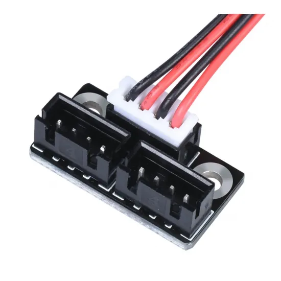
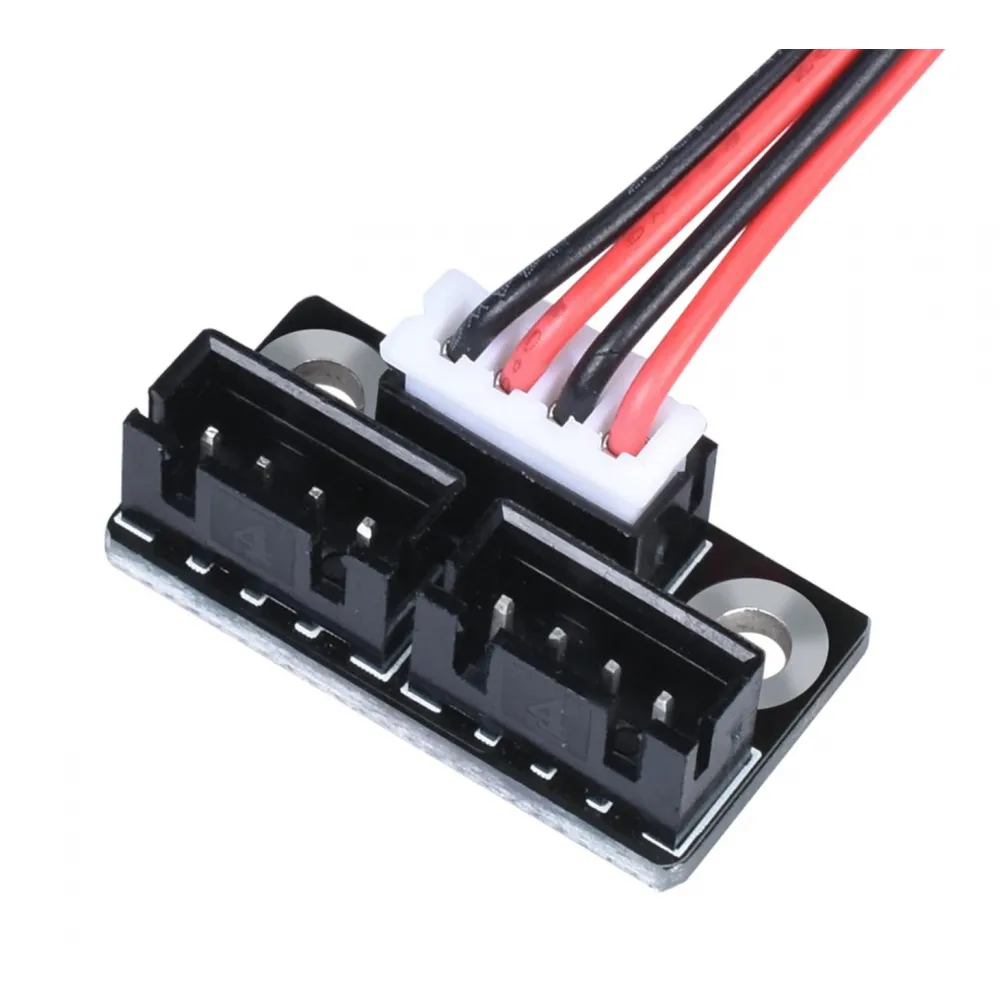
| Board connections | 3 keyed 4-way connectors |
| Control | One driver shared by both motors |
| Typical use | Dual Z motors on 3D printers |
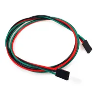
| Contents | 1 splitter board and 1 four-conductor cable |
Motor compatibility
For balanced operation, use two matching motors with the same model, rated current, resistance, inductance, step angle and coil wiring. It may, for example, be used with two equivalent units of a 42-40 NEMA 17 stepper motor, provided the driver, mechanics and wiring are suitable.
Both motors must present their coils in the same pin order. Wire colours are not a universal pinout standard: identify each coil pair and check the motor and controller-board pinout before connection. A physically matching plug does not by itself guarantee an identical electrical order.
If the machine geometry requires one motor to rotate in the opposite direction, reverse just one coil pair on that motor. Change any pin positions only while the machine is fully powered off and disconnected.
Driver current and available torque
When two equivalent motors are wired in parallel, the current supplied by the driver is shared approximately between them. Keeping the setting used for a single motor may leave less current and torque available to each motor; increasing it without checking the limits may overheat the driver, motors, connectors or splitter board.
The driver must support the total current required by the pair and have sufficient cooling. This module does not increase the driver's capacity, regulate current, or add thermal or short-circuit protection.
Installation and checks
- Switch the machine off, disconnect its power supply and allow the electronics to discharge.
- Identify both coils on each motor and verify the order of all four pins.
- Use the supplied cable between the driver output and one port on the splitter.
- Connect both motors to the remaining ports without forcing or displacing the terminals.
- Check manually that both lead screws or mechanisms move freely and carry a similar load.
- Perform the first test at low speed over a short distance, ready to cut the power.
- Verify that both sides move in the required direction, remain aligned and do not miss steps.
- Monitor driver and motor temperatures during a progressive test.
Never connect or disconnect a motor while its driver is powered. Energy stored in the coils can produce voltage spikes capable of damaging the controller.
Marlin, Klipper and RepRapFirmware configuration
The splitter does not create a second axis or a second driver. Steps per millimetre, microstepping and the overall direction remain as for one motor because both motors receive exactly the same signals.
- Marlin: retain a single Z axis. On configurable Trinamic drivers,
M906can report or set the channel current in mA; for potentiometer-adjusted drivers, follow the VREF procedure for the exact revision. - Klipper: retain a single
[stepper_z]section. On a TMC driver,run_currentsets the total RMS current for that driver, not an independent value for each motor. - RepRapFirmware: both motors remain assigned to one driver, and
M906sets that channel's current.
Parallel dual-Z limitations
Because both motors share one controller, the firmware cannot move each side of the Z axis separately. This arrangement does not support independent automatic alignment through G34, Z_TILT_ADJUST, or equivalent features that require one driver per motor.
The two sides of the gantry may lose synchronisation if one lead screw is turned by hand, the motors are disabled, or one motor misses steps. Check the gantry alignment periodically and consider mechanical belt synchronisation where the machine design calls for it. Automatic alignment with two independently driven Z motors requires a controller board with two separately controllable drivers.
Compatibility is not determined by printer size alone: consider axis mass, friction, lead-screw lead, speed, required torque and the driver's thermal capacity.
Contents
- 1 parallel dual-motor splitter module.
- 1 four-conductor cable.
Motors, stepper drivers, controller board and other wiring are not included.