

- Stock: Out of Stock
- Model: Robin-Nano

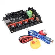
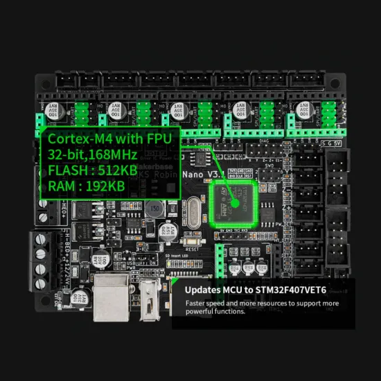
The MKS Robin Nano V3.1 is a 32-bit control board for building or upgrading a 3D printer's electronics. This revision uses an STM32F407VET6 at 168 MHz, with 512 KB flash and 192 KB RAM, and accepts replaceable stepper drivers. It offers connections for two extruders, a heated bed, display, fans and other common peripherals. The final setup depends on your printer's components and chosen firmware.
This is V3.1, not V3.0: the revisions share parts of their design and pin map but use microcontrollers with different flash capacities. Always check the revision printed on the board before compiling or installing firmware.
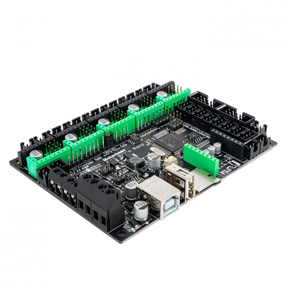
Connections and features
- 12 or 24 V board supply: choose a suitable power supply and components. Check the voltage and current requirements of the bed, heater cartridges, fans and motors separately.
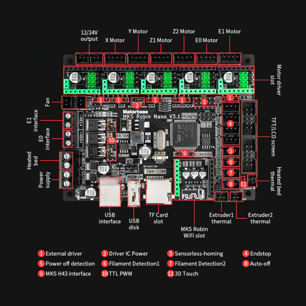
- Five driver sockets: X, Y, Z, E0 and E1. There are six motor connectors because Z1 and Z2 share the same Z driver. Two Z motors can be connected, but this board alone cannot adjust them independently.
- Heating and temperature: HE0 and HE1 outputs for two extruder heaters, a heated-bed output and three temperature inputs. Configure each thermistor or probe in firmware for the actual sensor fitted.
- Fans: two controllable outputs, FAN1 and FAN2. Firmware determines whether an output serves part cooling, hotend cooling or another purpose; do not infer its function from the connector name alone.
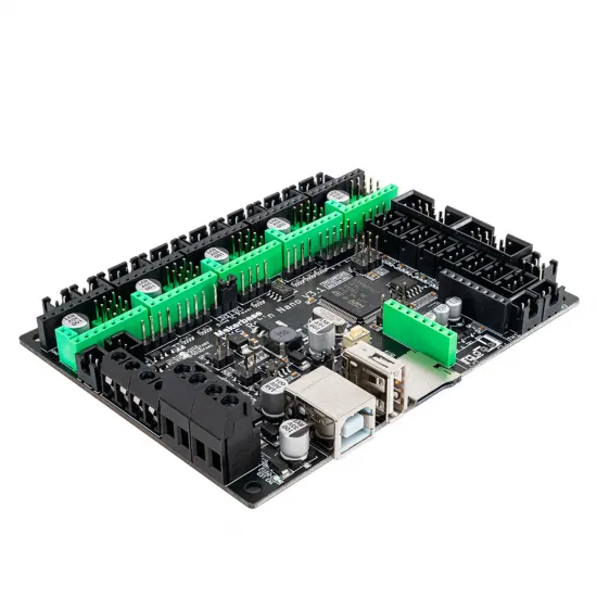
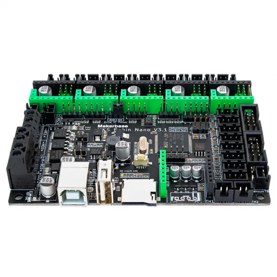
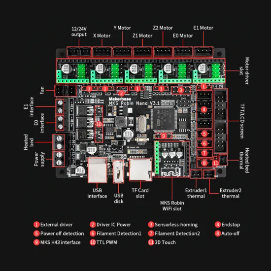
- Communication and expansion: USB device connection, USB flash-drive port, TF/microSD slot, EXP display connectors, endstops, BLTouch-type probe input, filament detection and a socket for an MKS Wi-Fi module. A socket does not mean the corresponding accessory is included.
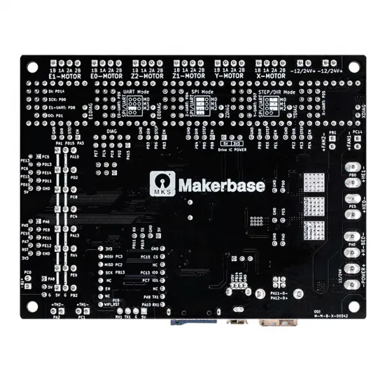
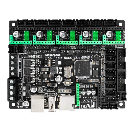
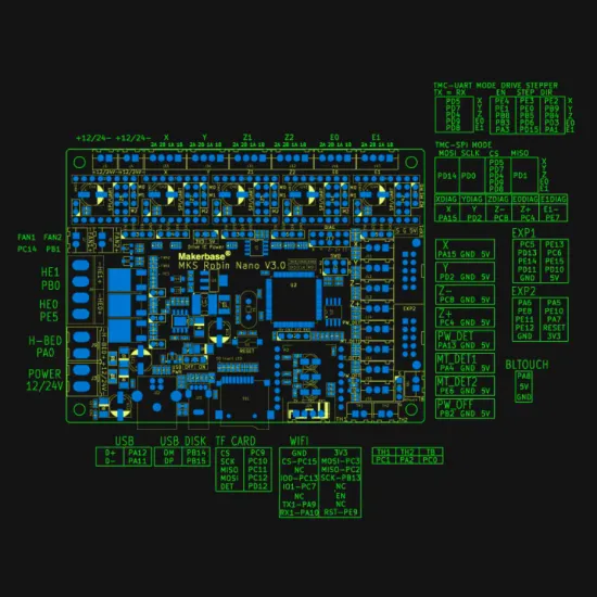
The following image shows the main connections of V3.1. In text: 12/24 V power, X/Y/Z1/Z2/E0/E1 motors, HE0/HE1 and H-BED heaters, FAN1/FAN2, TH1/TH2/TB temperature inputs, endstops, display and probe. Check the markings on your own board before wiring.
Stepper drivers and displays
The sockets accept suitably sized replaceable drivers. For UART or SPI operation, physical fit is not enough: the driver's pinout and orientation, board jumpers and firmware settings must all match. For a TMC2209 build, see our MKS TMC2209 V2.0 driver and prepare the appropriate UART configuration. Disconnect all power before fitting or changing a driver, then check orientation and motor current before moving an axis.
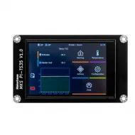
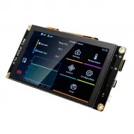
Makerbase documents display connections for the MKS TS35, H43 and Mini12864 V3 families, among others. Compatibility with a particular display depends on its revision, cable orientation, interface and firmware; a similar-looking LCD or TFT connector does not guarantee plug-and-play operation.
Marlin setup
- Start with a Marlin release that includes
BOARD_MKS_ROBIN_NANO_V3_1; do not selectBOARD_MKS_ROBIN_NANO_V3. The V3.1 build environments belong to themks_robin_nano_v3_1family. - Set your actual printer's kinematics, travel limits, motor directions, endstops, steps or microsteps, driver types, extruder count, display and probes. Select each temperature sensor's table or curve from the real sensor specification, not a generic firmware example.
- Build for this board and display. If using an MKS graphical interface, also check whether your firmware version needs display assets. Follow the update procedure for the selected firmware branch; do not load a V3.0 binary as if it were equivalent.
- At first startup, check that all ambient temperature readings are plausible before enabling heaters. Then test one axis and endstop at a time, fan control and thermal safeguards.
Klipper setup
Klipper provides a Robin Nano V3 pin-map example. It specifies STM32F407, a 48 KiB bootloader and USB communication. Makerbase describes placing the compiled firmware on a TF card as Robin_nano_v3.bin and restarting the board. The file is a starting point, not a ready-made printer.cfg for your printer.
Before printing, replace the example USB device path with the identifier of your own board, enter your printer's dimensions and motor settings, select the drivers and temperature sensors actually installed, and calibrate the heaters and extruder. Do not copy example PID values, thermistor types, endstop positions or motion limits as if they were Robin Nano specifications. An MKS touchscreen is not automatically a Klipper user interface either: verify support for the particular display and software environment you plan to use.
The official V3.1 hardware documentation includes the pinout, schematic and mounting drawing for this revision. Consult it before assigning an auxiliary pin or making an unfamiliar connection.
Size and mounting
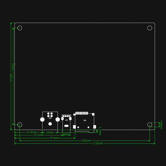
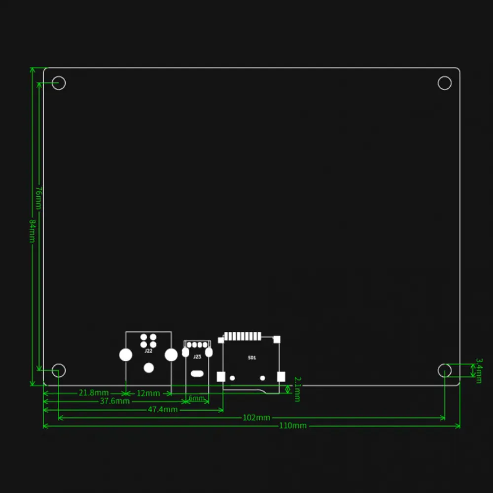
Nominal board size is 110 × 84 mm; the mounting drawing shows 102 × 76 mm hole-centre spacing and approximately 3.4 mm mounting holes. Leave additional clearance for connectors, cables, driver cooling and access to USB and microSD.
Is it right for you?
Choose it if you want a 32-bit controller with interchangeable drivers for a 12 or 24 V 3D printer and can adapt wiring, firmware and settings to your machine. Choose another solution if you need a drop-in replacement for a specific branded printer, independently controlled dual-Z motors or guaranteed plug-and-play operation with any display or driver.
Before installation: work with all power disconnected, verify polarity and voltage at each connection, and consult the V3.1 schematic. Drivers, display, power supply, sensors and other accessories are selected for the particular build; the board photographs show empty driver sockets.