Menu
Your Cart

16 AWG Flexible Heated-Bed Wire Pair – 50cm with Terminals

16 AWG Flexible Heated-Bed Wire Pair – 50cm with Terminals
2.25€
Ex Tax: 1.86€
  • Stock: 34
  • Model: Cable-16AWG-50cm-01

Fast shipping from Spain
Delivery from 24 hours and free shipping available in mainland Spain.
Stock on hand
Shipped quickly from Spain, with a full VAT invoice.
Secure & flexible payment
Pay by card, PayPal or bank transfer.
Expert technical support
Over 10 years helping customers with components and compatibility.

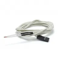
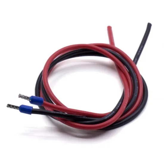
Pair of flexible 16 AWG wires, one red and one black, prepared for connecting a heated bed to a 3D printer controller board. Each conductor is approximately 50cm long and has a pre-insulated pin terminal fitted to one end for connection to a compatible terminal block.

The wires use stranded tinned-copper conductors with flexible silicone insulation. This configuration is used in our 3DSteel and P3Steel printers, but it can also be used in other machines when the length, wire size, termination and electrical requirements are suitable.

Main features

  • Quantity: 2 separate wires.
  • Colours: 1 red and 1 black.
  • Wire gauge: 16 AWG.
  • Approximate nominal cross-sectional area: 1.31mm².
  • Length of each wire: approximately 50cm.
  • Conductor: stranded tinned copper.
  • Insulation: flexible silicone.
  • Indicated stranded-conductor diameter: approximately 1.53mm.
  • Indicated outside diameter: approximately 3mm.
  • One end of each wire has a pre-insulated pin terminal.
  • The opposite end is supplied without a bed-specific connector.

Compatibility

  • Used in HTA3D 3DSteel and P3Steel printers.
  • Suitable for RAMPS electronics with compatible terminal blocks.
  • Can be used with certain SKR boards and other controllers when their terminals accept the pin and wire size.
  • Can be adapted to other DC heated-bed 3D printers after checking their electrical requirements.

Compatibility with a particular board or printer may be partial. Check heated-bed voltage, power and current, required cable length, controller-output capacity and terminal dimensions. A physically matching connection does not guarantee that the controller can safely drive the load directly.

Heated-bed connection

The pin terminals are intended for the controller side when its terminal blocks are compatible. The opposite end must be terminated according to the bed design, using soldering, a crimp terminal or a dedicated connector as appropriate.

Heated beds can draw substantial current. If the load exceeds the controller output rating, a correctly sized external MOSFET module may be required. This must be determined from the actual specifications of the heated bed and controller board.

Installation recommendations

  • Completely disconnect power before working on the circuit.
  • Check heated-bed polarity and rated voltage.
  • Make sure that the terminals are fully inserted and firmly secured.
  • Provide strain relief so that bed movement does not pull directly on the electrical connections.
  • Avoid tight bends and continuous rubbing against the machine frame.
  • Perform an initial test and check the temperature of the wires, terminals and connectors.
  • Periodically check terminal tightness as part of printer maintenance.

Related wires

Package contents

  • 1 × Red 16 AWG flexible wire, approximately 50cm long, with a terminal on one end.
  • 1 × Black 16 AWG flexible wire, approximately 50cm long, with a terminal on one end.

Write a review

Note: HTML is not translated!
Bad Good
Captcha

EQUIPMENT START UP:

  1. Check that the mains voltage matches the input selected for the source (110/220v)
  2. Connect the power supply to the mains to check the output voltage (12/24v)
  3. The output voltage is adjustable, if it differs from the one you want for your application you can turn the regulator, preferably with the equipment off. Never use a metal screwdriver with the equipment on to make this adjustment.
  4. (Depending on the model) This power supply has a regulated fan, it will turn when it has load, check periodically and in the first use that the fan is activated correctly.


SAFETY INSTRUCTIONS COMPACT POWER SUPPLY:

  • Dimension the installation correctly, with an appropriate safety factor.
  • Never block or hinder the fan's air output. 
  • Before connecting the equipment to the power supply, check that the available mains voltage corresponds to the voltage value of the equipment.
  • Connect the mains cable of the equipment to a grounded power outlet.
  • Do not place the equipment on wet or damp surfaces.
  • Do not expose the equipment to direct sunlight or extreme temperatures.
  • Do not expose the equipment to moisture.
  • Do not exceed the maximum input voltage allowed.
  • Comply with the warning and information labels on the equipment.
  • Wear dry clothes and rubber shoes to ensure insulation.
  • Do not insert metal objects into the equipment through the ventilation slots.
  • Do not place containers full of liquids on the equipment (danger of short circuit in case of shock).
  • Do not use the equipment near strong magnetic fields (motors, transformers, etc.).
  • Do not expose the equipment to strong shocks or vibrations.
  • Allow the unit to stabilize at room temperature before taking measurements (important for accurate measurement).
  • Do not modify the equipment in any way.
  • The equipment must be opened for service or repair by qualified personnel. It is recommended that repair work be carried out in the presence of a second person trained to perform first aid if necessary.
  • Keep the power source away from children.
  • Before cleaning the box, pull out the plug from the socket. Clean only with mild household cleaner. Make sure that no water gets inside the equipment to avoid possible short circuits and damage to the equipment.