- Stock: Out of Stock
- Model: IR-Module
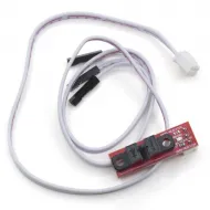
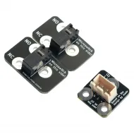
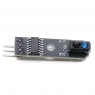
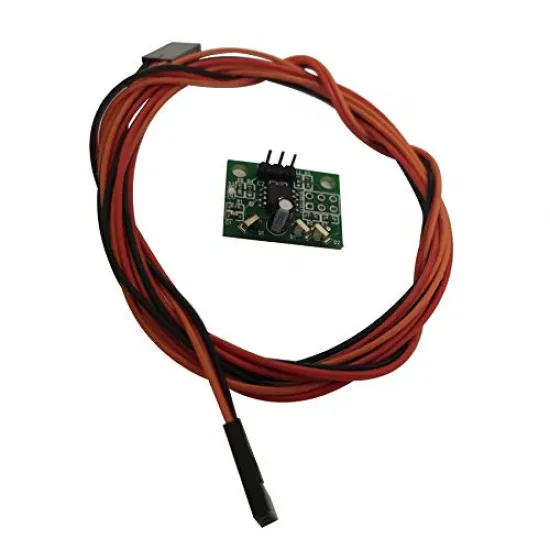
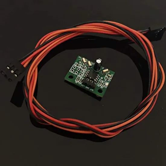
The Mini IR module is a non-contact optical probe designed to measure the position of a 3D printer build surface. Its compact 24 × 18mm circuit board makes it suitable for toolheads with limited space, including custom Cartesian, CoreXY and delta machines.
This revision uses a differential optical architecture. Two infrared emitters illuminate the surface from different angles, while a central receiver compares the reflected light. When the target distance is reached, the output changes state and the firmware can record the height of that point.
As a fixed probe, it has no deployable pin, servo or moving mechanism. This provides a lightweight and quiet measuring system, although its behaviour depends on the optical properties of the build surface.
Main features
- Type: differential infrared optical probe.
- Operation: non-contact proximity detection.
- Nominal PCB dimensions: 24 × 18mm.
- Connection: three conductors for power, ground and signal.
- Design supply voltage: regulated 3.3V or 5V, depending on the controller connection.
- Indicator: integrated status LED.
- Installation: fixed probe with no pin deployment or retraction.
- Firmware: configurable in Marlin, Klipper and RepRapFirmware.
Do not connect this module to 12V or 24V. Before applying power, check the VCC, GND and OUT markings on the PCB and the controller pinout. Do not rely only on cable colours or connector position, as pin order can vary between controller boards.
Build-surface compatibility
Infrared detection can measure materials that an inductive probe cannot detect directly, including glass. However, compatibility is not universal: the trigger point depends on the amount of reflected infrared light and on which layer of the build platform produces the dominant reflection.
- Glass: it can work correctly, particularly when placed above a dark, low-reflectivity backing surface.
- Glass over bright aluminium: infrared light may pass through the glass and reflect from the aluminium, changing the measured height. A dark matt layer between them may improve operation.
- PEI: some sheets are partially transparent to infrared light. The adhesive, colour and underlying plate may affect triggering.
- Bright aluminium or mirrors: strong reflections may produce a different or unstable response.
- BuildTak and opaque surfaces: these generally provide a more clearly defined reflection, but each installation must still be tested.
Hairspray, adhesive, PVA, polyimide tape, dirt or a change of build sheet can alter the trigger height. Whenever the surface is changed, check repeatability again and recalibrate the Z offset.
Mechanical installation
- Mount the board rigidly and vertically, with the optical components facing the bed.
- Make sure that the mount, wiring and cooling ducts do not obstruct the emitters or receiver.
- Keep a sensible distance from the heater block to reduce direct heat exposure.
- Configure the actual X and Y offsets of the optical sensing point.
- Limit the mesh area so that the probe remains above the build surface at every point.
- Check the signal change at a safe height before performing the first Z home.
The trigger height must not be treated as a fixed value. It varies with the surface, temperature, mount and individual sensor and must be measured after installation.
Marlin configuration
In Marlin this sensor is configured as a fixed probe, not as a BLTouch:
#define FIX_MOUNTED_PROBE
The output must be connected to a compatible probe or endstop input. If it is physically connected to Z-min, the relevant option may be:
#define Z_MIN_PROBE_USES_Z_MIN_ENDSTOP_PIN
Do not enable this option when the signal is connected to another input. Trigger polarity must be established through testing and configured with Z_MIN_PROBE_ENDSTOP_INVERTING when required; there is no universal value for every board.
Before approaching the nozzle to the bed, use M119 to check the probe state both away from the surface and with a representative sample close to it. If the probe replaces the Z endstop, it is normally appropriate to configure:
#define Z_SAFE_HOMING
Probe offsets, measuring margins and a safe downward movement limit must also be configured for the actual machine geometry.
Klipper configuration
In Klipper it should be configured through a [probe] section:
[probe]
pin: PROBE_PIN
x_offset: X_VALUE
y_offset: Y_VALUE
z_offset: INITIAL_VALUE
speed: CONSERVATIVE_SPEED
The ! prefix for signal inversion and the ^ prefix for a pull-up resistor should only be added when required by the controller and confirmed by testing.
First check the signal using:
QUERY_PROBE
Then calibrate the trigger height with PROBE_CALIBRATE and check repeatability with PROBE_ACCURACY. It is advisable to repeat the latter test both when cold and at the normal printing temperature to identify thermal or optical variation.
If the probe is used as the Z endstop, configure:
endstop_pin: probe:z_virtual_endstop
In this case, remove position_endstop from [stepper_z] and add a [safe_z_home] section whose position keeps the optical sensing point over the build surface.
RepRapFirmware configuration
The connection mode depends on the Duet controller generation:
- Duet 2 and earlier boards: the Mini Differential IR architecture is normally connected to 3.3V, GND and IN on the Z-probe connector and configured using mode 1 in
M558. - Duet 3: it is connected to 3.3V, GND and the input of an IO port; the official documentation uses digital mode 8 in
M558.
; General outline for Duet 2
M558 P1 ...
; General outline for Duet 3
M558 P8 C"INPUT_PIN" ...
Pin names and the remaining parameters must be adapted to the exact board. X/Y offsets and the measured trigger height are configured with G31 after testing operation at a safe distance.
Checks before the first homing movement
- Identify VCC, GND and signal from the PCB and controller documentation.
- Power the probe only from a regulated 3.3V or 5V supply, as appropriate.
- Confirm that the LED and output change state as the actual build surface approaches.
- Take several readings at the same position to verify repeatability.
- Test the system at the normal bed operating temperature.
- Perform the first downward movement slowly and be ready to stop the machine.
Choosing between probe technologies
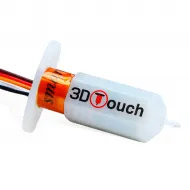
This IR probe is useful when a compact, fixed and non-contact solution is required, particularly for glass and other non-metallic surfaces. When a contact measurement that is less dependent on optical finish is preferred, consider the Fysetc 3DTouch sensor.
Machines with a suitable metallic build platform may also use the TL-Q5MC2-type inductive proximity sensor. These alternatives are not direct replacements, as their mounts, wiring and firmware configuration are different.
Contents
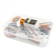
- 1 Mini IR module.
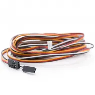
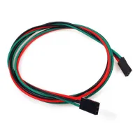
- 1 three-wire connection cable.