

- Stock: 3
- Model: Sensor-Prox-V
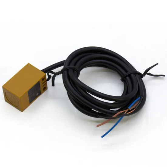
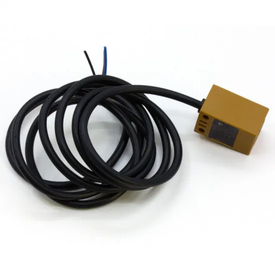
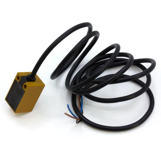
Three-wire TL-Q5MC2-type inductive proximity sensor with an NPN normally-closed output and a nominal sensing distance of 5mm. It detects metal surfaces without physical contact and may be used as a fixed probe in 3D printers, CNC machines and automation systems.
This format has traditionally been used in Voron configurations for bed measurement, Bed Mesh and gantry-alignment operations. Compatibility with a particular machine depends on the mechanical mount, metal target, controller board and signal-interface circuit.
This is a TL-Q5MC2-type compatible product and is not presented as an original Omron sensor.
Main features
- Sensor type: inductive proximity.
- Electrical configuration: three wires.
- Output type: NPN, normally closed — NC.
- Declared supply range: 6–36V DC.
- Typical operating voltage: 12 or 24V DC.
- Nominal sensing distance: 5mm.
- Detected target: metal.
- Declared response time: less than 2ms.
- Integrated LED indicator.
- Approximate cable length: 1.05m.
Nominal dimensions
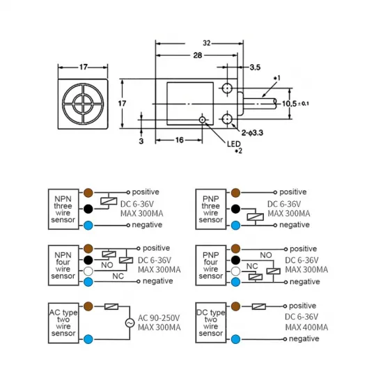
- Body: approximately 28 × 17 × 17mm.
- Length including cable outlet: approximately 32mm.
- Mounting holes: 2 × Ø3.3mm according to the drawing.
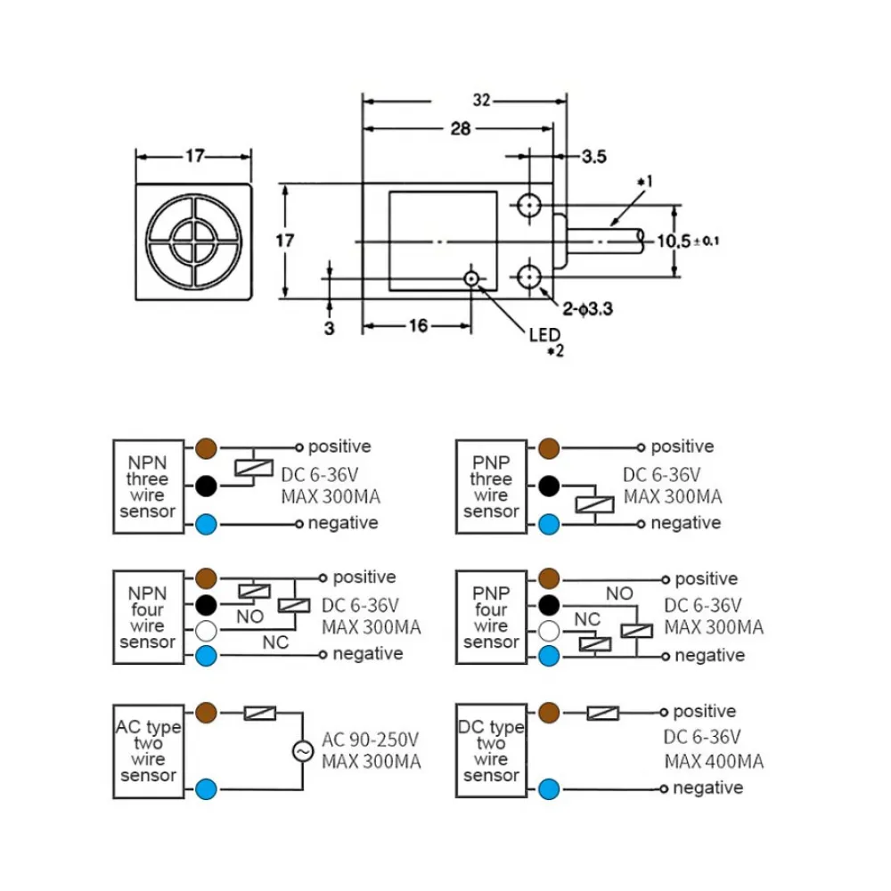
The image includes generic diagrams for several sensor families. Only the three-wire NPN arrangement applies to this product.
Wiring
- Brown: positive sensor supply, between 6 and 36V DC.
- Blue: 0V or supply ground.
- Black: normally-closed NPN signal output.
With an NPN NC output, the transistor normally conducts when no metal is present and changes state when the target is detected. The logic level seen by the firmware depends on the input circuit, pull-up resistor and configured inversion.
Important electrical warning
Do not connect the black signal wire directly to a 3.3 or 5V microcontroller input without first checking the controller circuit. The sensor is normally powered from 12 or 24V, and an unsuitable connection may expose the logic input to a damaging voltage.
Depending on the controller, safe connection may require:
- A dedicated NPN-compatible input.
- An optocoupler.
- A protected or jumper-selectable probe input.
- An interface circuit specified by the board manufacturer.
- A BAT85 diode in certain traditional Voron configurations.
In the traditional Voron BAT85 circuit, the black band on the diode faces the probe rather than the microcontroller input. Do not automatically copy this arrangement when the controller already contains protection or a dedicated proximity-sensor interface.
Always follow the documentation for the exact controller model and revision. Never pull a logic input up to 12 or 24V unless the board manufacturer explicitly requires it.
Print-surface compatibility
The sensor detects metal. It does not directly detect glass, plastic, Kapton tape or PEI, although it may detect a metal sheet or bed beneath those materials.
The nominal 5mm distance is obtained under reference conditions. Actual sensing distance may be reduced by:
- Target-metal type.
- Target size and thickness.
- Coatings or intermediate printing surfaces.
- Sensor and bed temperature.
- Mounting position and rigidity.
Do not use the nominal 5mm specification as the installation safety margin. Operate at a shorter verified distance and preserve enough nozzle-to-bed clearance under the worst expected conditions.
Voron printer compatibility
The TL-Q5MC2 format appears in Voron startup documentation as a traditional inductive probe. It may be used in certain Voron 2.4, Voron Trident and other printer configurations fitted with a compatible mount.
Compatibility may be partial. Some current carriage, linear-rail and toolhead revisions replace the inductive probe with Klicky, Tap or eddy-current systems. Check the printed parts and bill of materials for the exact printer revision.
An inductive probe also:
- Requires a suitable metal reference surface.
- May change trigger height with temperature.
- Does not directly measure nozzle position.
- Requires X, Y and Z offset calibration.
Klipper configuration
In Klipper it is configured as a fixed probe using the [probe] section rather than [bltouch].
[probe]
pin: <protected input and actual controller pin>
x_offset: <measured on the machine>
y_offset: <measured on the machine>
z_offset: <calibrate on the machine>
speed: 5.0
samples: 3
sample_retract_dist: 3.0
This example only shows the structure. There is no universal value for pin, its ! inversion prefix or the ^ pull-up prefix. These depend on the controller and interface circuit.
Initial Klipper test
- Keep the nozzle safely away from the bed.
- Run
QUERY_PROBE. - Move a metal object towards the active face by hand.
- Run
QUERY_PROBEagain. - Confirm that the reported state changes consistently.
- Correct pin inversion if the logic does not match the intended configuration.
In the Voron reference configuration, once correctly configured, the probe should report open when it is away from the bed. Verify this before allowing any automatic Z movement.
After installation, use PROBE_ACCURACY to assess repeatability and PROBE_CALIBRATE to set the offset where required by the printer architecture.
Marlin configuration
In Marlin it should be configured as a fixed probe:
#define FIX_MOUNTED_PROBE
When connected to the Z-min input, the following option may be required:
#define Z_MIN_PROBE_USES_Z_MIN_ENDSTOP_PIN
When another connector is used, define the correct pin for the controller. The value of Z_MIN_PROBE_ENDSTOP_INVERTING must be selected from the actual reading rather than from the NC designation alone.
Before homing or levelling:
- Run
M119with the sensor clear. - Run it again with metal in front of the sensor.
- Confirm that the state changes correctly.
- Configure the probe offsets.
- Enable a safe homing procedure when required.
RepRapFirmware configuration
RepRapFirmware configures probes with M558 and defines trigger height with G31. This unit should be treated as a digital NPN probe, but the mode, pin and inversion depend on the Duet or compatible controller being used.
M558 P<mode> C"<actual pin, inverted when required>" ...
G31 P<calibrated trigger height>
The placeholders are deliberate. Do not copy a complete command from another machine because input circuits, protection and pin names differ between Duet 2, Duet 3 and compatible boards.
Mounting and calibration
- Use a rigid support compatible with the 17 × 17mm body.
- Keep the active face parallel to the metal target.
- Make sure that the sensor remains higher than the nozzle tip.
- Check the complete movement range for possible collisions.
- Protect the cable from tight bending and tensile loads.
- Calibrate with the bed at a representative printing temperature.
- Repeat calibration after changing the surface, mount or sensor.
Before the first automatic homing operation, test the probe while remaining ready to disconnect power. Do not rely on the LED alone: also verify the state received by the firmware.
Catalogue alternatives
- Klicky Probe kit for Voron printers.
- BTT MicroProbe V2.0.
- 3DTouch automatic bed-levelling sensor.
- BTT Eddy Duo high-speed levelling sensor.
Package contents
- 1 × TL-Q5MC2-type NPN NC inductive sensor with an approximately 1.05m cable.
Mounting bracket, connector, BAT85 diode, interface module and screws are not included.