

- Stock: 11
- Model: KlickyProbe-Fysetc

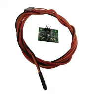
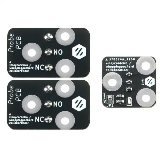
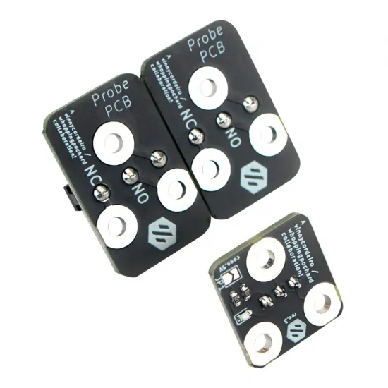
The Fysetc PCB Klicky Probe is a kit for building a removable, magnetically attached Z probe based on the PCB Klicky design. This version combines the operating principle of the Klicky Probe project with circuit boards that align the magnets, provide electrical contacts and add an optional status LED.
During probing, the toolhead collects the probe from a dock installed inside the printer. Once levelling is complete, it returns the probe to the dock so that the sensor does not remain next to the hotend during printing.
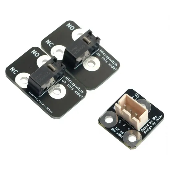
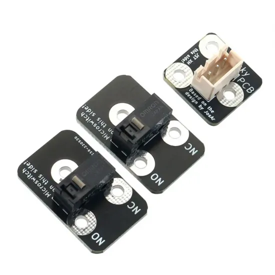
The kit includes two probes fitted with Omron D2HW-A201D microswitches, allowing one main probe and one spare to be assembled. The D2HW-A201D is a sealed ultra-subminiature SPDT switch with a pin-plunger actuator.
Important: this is a project for users experienced with mechanical assembly, wiring and firmware configuration. It is not a universal plug-and-play accessory.
PCB Klicky design advantages
- Removable magnetic attachment.
- Contact detection that does not depend on the build-surface material or optical finish.
- PCB construction that helps align magnets and electrical contacts.
- Two probe boards for building a main probe and a spare.
- Sealed Omron D2HW-A201D microswitches.
- Optional toolhead status LED.
- Passive operation possible without powering the LED.
- No permanent probe next to the hotend during printing.
Printer and toolhead compatibility
The wider Klicky ecosystem provides documentation for Voron V2.4, Voron V1.8, Voron Trident, Voron Legacy, Voron V0 and Voron Switchwire, together with community adaptations for RatRig V-Core, Mercury One and other CoreXY machines.
This does not mean that the PCB kit fits all those printers directly. Actual compatibility requires:
- A printed mount compatible with the carriage and toolhead.
- A free and reachable position for the dock.
- Sufficient travel for attaching and releasing the probe without collisions.
- A compatible probe or endstop input on the controller.
- Macros and coordinates adjusted to the actual printer geometry.
The original PCB Klicky files include a reference mount named AB_mount, developed for the corresponding project geometry. A suitable STL must be confirmed or adapted when using StealthBurner, alternative toolheads or modified carriages.
Klicky was developed, among other uses, as an alternative to the TL-Q5MC2-type inductive probe used on many Voron printers. Replacement may require changes to the mount, offsets, wiring, dock and firmware configuration and should not be considered direct on every machine.
Required printed parts
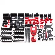
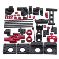
3D-printed parts are not included. They must be downloaded and printed from the PCB Klicky project or from an adaptation designed for the target printer.
The reference design includes files for:
- Heat-set toolhead PCB mount.
- Self-tapping-screw toolhead PCB mount.
- Heat-set probe body.
- XL probe body.
- Self-tapping-screw probe body.
- Modified dock front that retains the probe through a ferrous screw.
Files and original instructions are available from the PCB Klicky repository.
Magnet assembly
Magnet polarity determines whether the probe attaches correctly and whether the electrical contacts align. Before tightening the screws:
- Identify and mark the polarity of every magnet.
- Position the toolhead and probe PCBs without fully tightening them.
- Confirm that all three positions attract and that the probe has the correct orientation.
- Make sure the PCB sits completely flat against the printed component.
- Tighten gradually without bending or stressing the circuit board.
The M3 screw fitted to the back of each probe acts as the ferrous target for the dock magnet, helping retain the probe while it is not being used.
G, S and + connections
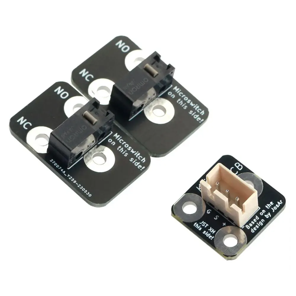
The toolhead PCB identifies its connections as:
- G: ground.
- S: probe signal.
- +: indicator-circuit supply.
The positive supply is optional. When only ground and signal are connected, the assembly can operate as a passive Klicky switch, but the status LED will not be available.
LED and operating-voltage configuration
The PCB incorporates an LED, resistors and a solder jumper marked J1 or JP1. Its configuration depends on the supply voltage and probe-input circuit:
- Passive operation: leave the positive terminal disconnected. The probe operates as a conventional switch without an LED.
- 3.3V or 5V operation: the project allows J1 to be bridged for the low-voltage path.
- 24V installations: the original design uses J1 open and a 2.2kΩ resistor, but requires a protected input or the appropriate interface circuit for the controller.
Never apply 24V directly to a 3.3V or 5V GPIO. Inspect the actual state of J1 and consult the controller schematic before powering the LED. If there is any uncertainty, begin with the passive two-wire configuration.
Recommended fail-safe logic
The original configuration is designed so that a missing probe, poor attachment or interrupted connection produces a safe state. Verify all three conditions before any Z movement:
- Probe detached: firmware should report
TRIGGERED. - Probe attached and switch released: it should report
open. - Microswitch pressed: it should return to
TRIGGERED.
If these three states are not obtained, do not perform Z homing, gantry levelling or bed probing.
Klipper configuration
Klipper is the main firmware ecosystem for which Klicky was developed. Configure it as a switch using a [probe] section, not [bltouch]:
[probe]
pin: PROBE_PIN
x_offset: X_OFFSET
y_offset: Y_OFFSET
z_offset: INITIAL_Z_OFFSET
The MCU pin, inversion prefix ! and pull-up prefix ^ depend on the controller and wiring. They must not be copied from another printer without verification.
Check the logic using:
QUERY_PROBEKlicky macros manage probe attachment, state checking and docking. At minimum, the following values must be adapted:
- Dock position.
- Approach and exit coordinates.
- Attachment speeds.
- X and Y offsets.
- Auto-Z or check position, when used.
- Safe movement limits.
The PCB version centres the microswitch differently from the original printed Klicky probe. Existing dock coordinates may therefore need adjustment. The project documentation shows an approximately 2mm change on one reference printer, but that value is not universal.
Recommended commissioning sequence:
- With the printer powered off, check continuity and verify that there are no shorts.
- Run
QUERY_PROBEwith the probe detached. - Attach it manually and run
QUERY_PROBEagain. - Press the microswitch manually and check the state once more.
- Test attachment and docking macros away from the bed.
- Verify that the probe cannot detach during normal movements.
- Run
PROBE_ACCURACY. - Calibrate the offset with
PROBE_CALIBRATE. - Only then test
QUAD_GANTRY_LEVEL,Z_TILT_ADJUSTor the required bed mesh.
Updated macros and printer-specific documentation are available from the Klicky Probe repository.
RepRapFirmware use
The Klicky project also includes work for RepRapFirmware. The microswitch is configured as a digital probe, while attachment and docking are handled by movement macros.
The M558 pin and mode must be adapted to the controller, while G31 defines probe offsets and trigger height. Attachment and docking macros must initially be tested away from the bed.
There is no universal configuration for every Duet controller: input names, polarity, dock coordinates and movements depend on the printer and RepRapFirmware version.
Marlin use
The D2HW-A201D can electrically be read as a digital probe or endstop. However, Marlin does not provide the complete Klicky docking sequence by itself.
Automated Marlin use requires carefully adapted movements and custom G-code for the dock, together with checks that prevent probing when the sensor is not attached. This kit should therefore not be considered plug-and-play for Marlin; the most developed support is available for Klipper, with additional project work for RepRapFirmware.
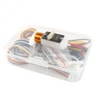
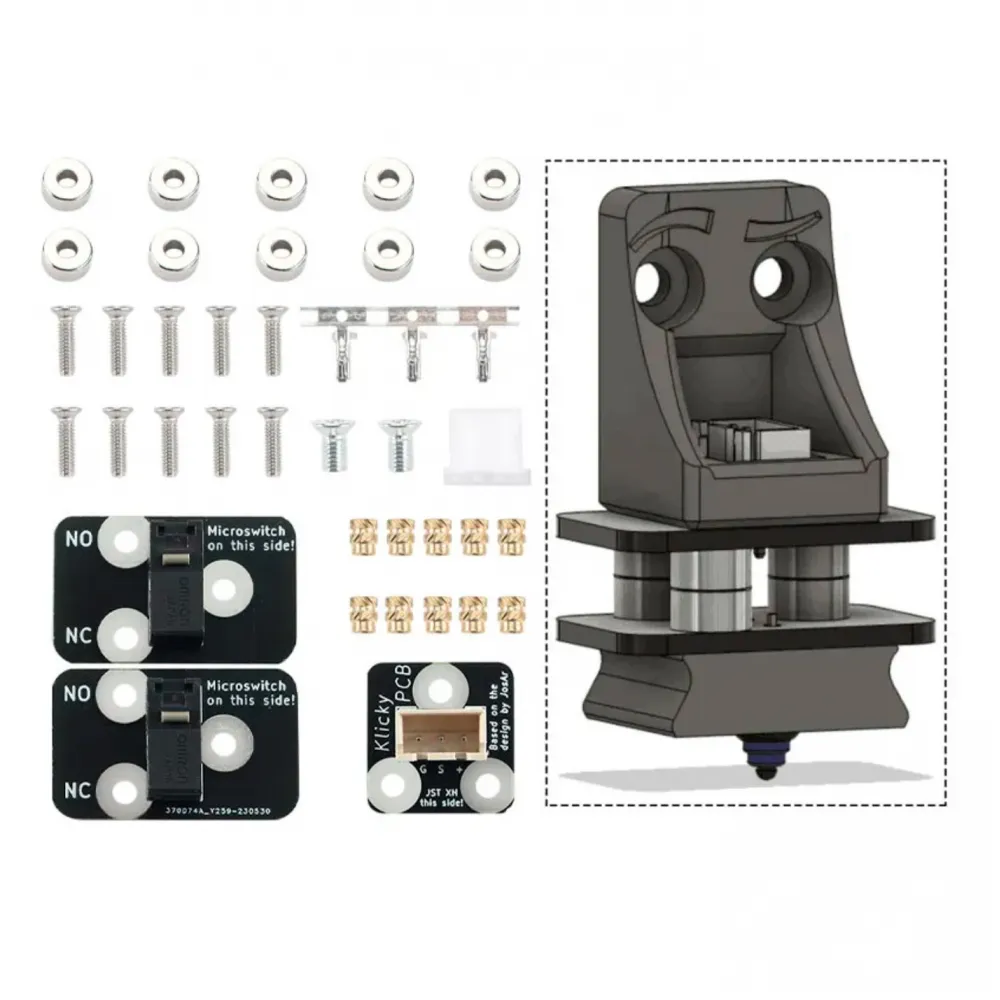
Kit contents
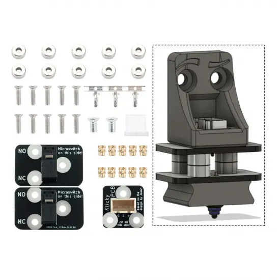
- 1 toolhead interface PCB with LED and JST-XH connector.
- 2 probe PCBs with Omron D2HW-A201D microswitches.
- 5 pairs of countersunk magnets, 10 magnets in total.
- 10 M2 × 3.2 × 4mm heat-set inserts.
- 10 M2 × 8mm flat-head screws.
- 2 M3 × 6mm flat-head screws for dock retention.
- 1 three-way JST-XH housing.
- 3 crimp terminals.
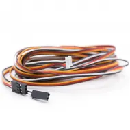
Printed parts and a completed connection cable are not included.