Menu
Your Cart

2m Extension Cable for 3DTouch Sensor – 5-Pin to 3-Pin and 2-Pin Connectors

2m Extension Cable for 3DTouch Sensor – 5-Pin to 3-Pin and 2-Pin Connectors
Out of Stock
2m Extension Cable for 3DTouch Sensor – 5-Pin to 3-Pin and 2-Pin Connectors
3.15€
Ex Tax: 2.60€
  • Stock: Out of Stock
  • Model: Cable-3DTouch-2m
Product out of stock
This product is out of stock, we will try to replenish it as soon as possible. You can request a notice by clicking on the green button (except discontinued products).

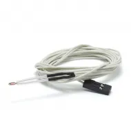
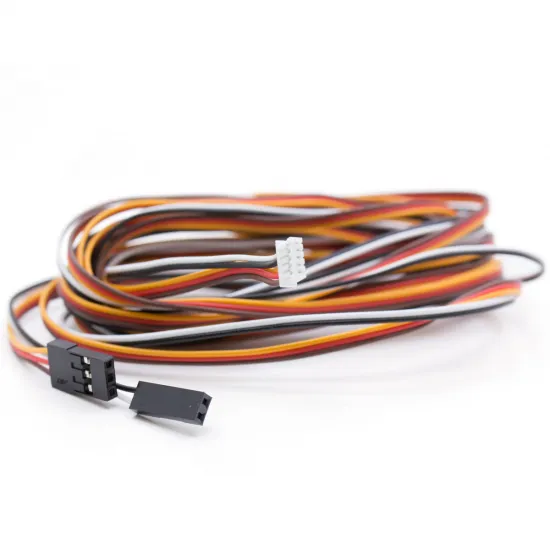
Two-metre cable for connecting a 3DTouch automatic bed-levelling sensor to a 3D printer controller board. It is useful for larger machines or for routing the probe wiring neatly through the toolhead, drag chain and frame to the electronics enclosure.

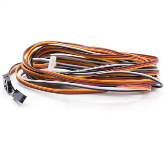
The sensor end has a white 5-position connector. At the controller end, the conductors are divided into a 3-position female connector for probe power and control, and a separate 2-position female connector for the trigger signal.

Main features

  • Application: wiring for a 3DTouch automatic bed-levelling sensor.
  • Approximate length: 2 metres.
  • Number of conductors: 5.
  • Sensor-side connector: white 5-position housing.
  • Controller-side connectors: 3-position and 2-position female housings.
  • Colour-coded conductors.
  • Split configuration for separate probe-control and endstop-signal connections.

Typical functional arrangement

On conventional 3DTouch sensors, the five conductors are normally divided into two groups:

  • Three-conductor group: power, ground and the control signal used to deploy or retract the probe.
  • Two-conductor group: ground and the trigger signal connected to the probe or Z-endstop input.

The commonly used colour arrangement is:

  • Brown: power ground.
  • Red: power supply.
  • Yellow or orange: control signal.
  • Black: trigger-signal ground.
  • White: trigger signal.

This arrangement is a reference rather than a universal guarantee. Some sensors, boards or cable versions may use a different order even when their connectors physically fit. Always check the controller labels, sensor documentation and continuity of every conductor before applying power.

Compatibility

Designed for use with 3DTouch automatic bed-levelling sensors that use the same five-conductor connection.

It may also be suitable for the Fysetc 3DTouch sensor and other probes based on a similar architecture, provided that the following match:

  • Sensor connector type and orientation.
  • Actual order of the five conductors.
  • Probe supply voltage.
  • Controller-board pin arrangement.
  • Trigger-input and control-pin configuration.

Compatibility with an original BLTouch or another probe must not be assumed merely because it uses five wires. Check the pinout of the exact product version.

Connecting to the controller board

Controller boards do not use a universal probe-pin arrangement. Some have a dedicated five-pin port, others separate the probe control and Z input, and certain installations may require the terminals to be repositioned inside their housings.

Before connecting:

  1. Identify the power, ground, control and probe-signal pins on the controller board.
  2. Check the voltage supplied by the power pin.
  3. Verify continuity between every terminal in the white connector and the black connector housings.
  4. Reposition terminals only when required by the controller documentation and when you can remove them without damage.
  5. Check the complete order again before switching the printer on.

Reversing power, ground and signal connections may damage the probe or controller board.

Firmware configuration

The cable does not determine the Marlin, Klipper or RepRapFirmware configuration. Firmware settings depend on the controller model, pins being used, probe type and mounting position.

  • Marlin: support for a BLTouch/3DTouch-type probe must be enabled, with the probe input and control signal assigned correctly.
  • Klipper: the actual control and trigger pins must be entered in the probe configuration, including any logic inversion required by the board.
  • RepRapFirmware: the probe must be assigned to suitable inputs and outputs using the configuration for the specific controller board.

There is no single safe configuration line for every controller. Always use the documentation for the exact board revision.

Recommendations for a 2-metre signal cable

  • Route it away from heater, heated-bed and motor wiring whenever possible.
  • Avoid long parallel runs next to high-current cables.
  • Make sure that no axis movement places the cable under tension.
  • Provide strain relief near both the probe and controller.
  • Prevent the cable from snagging or exceeding the available bend radius.
  • Perform several deployment, retraction and trigger tests before automatic levelling.
  • Check probe repeatability after installation.

Because this is a relatively long signal connection, poor routing or proximity to power wiring may contribute to electrical interference. If false triggers or unstable readings occur, first inspect the routing, connectors, continuity and electrical configuration.

Package contents

  • 1 × 2-metre 3DTouch sensor cable with a 5-position connection at one end and separate 3-position and 2-position connections at the other.

Write a review

Note: HTML is not translated!
Bad Good
Captcha