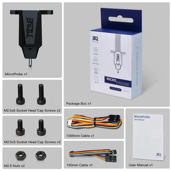


- Stock: 9
- Model: BTT Micro Probe

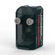
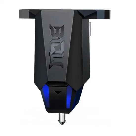
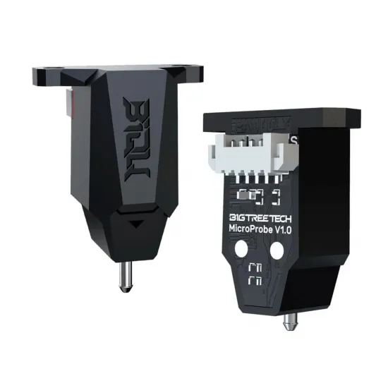
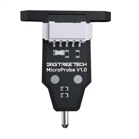
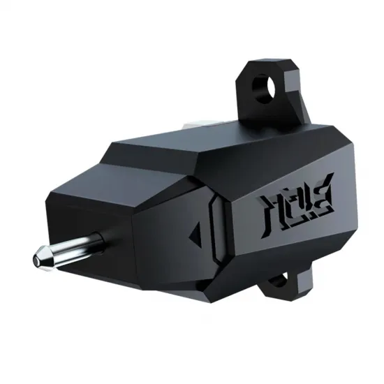
The BIGTREETECH MicroProbe V2.0 is a compact, lightweight contact probe designed to measure a 3D printer build surface. Its deployable metal pin physically touches the bed, allowing it to work with glass, PEI, steel, aluminium and other stable surfaces without depending on magnetic or optical properties.
The resulting measurements can be used for Z homing, multi-motor gantry alignment or bed-mesh compensation. The probe does not mechanically correct a poorly assembled bed; it provides the data required by the firmware to compensate for small height variations.
MicroProbe V2 must not be configured as a BLTouch. Although it uses five wires in a similar physical arrangement, its control signal and operating method are different. BIGTREETECH warns that an incorrect firmware configuration may cause permanent hardware damage.
Main features
- Brand: BIGTREETECH / BIQU.
- Version: MicroProbe V2.0.
- Type: contact probe with deployable and retractable pin.
- Supply voltage: 5V.
- Control logic: compatible with 3.3V and 5V signals.
- Detection output: open-drain, active low on V2.
- Declared standby current: 19mA.
- Declared operating current: 350mA.
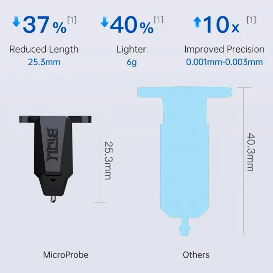
- Weight: approximately 6g.
- Maximum declared chamber ambient temperature: 60°C.
- Connector: five pins with 1.25mm pitch.
- Probe pin: removable and replaceable.
- Manufacturer-declared service life: over 10 million cycles.
Declared repeatability
BIGTREETECH specifies the result as standard deviation under two test conditions:
- 0.001mm at 24°C ambient temperature and a 60°C bed.
- 0.003mm at 60°C ambient temperature and a 100°C bed.
These values represent repeatability under the manufacturer’s test conditions, not guaranteed absolute accuracy on every printer. Mount rigidity, toolhead construction, probing speed and operating temperature also affect the result.
Nominal dimensions
- Width: 21.93mm.
- Depth: 15.60mm.
- Height with pin extended: 28.10mm.
- Height with pin retracted: approximately 25.30mm.
- Mounting-hole centre distance: 17mm.
- Mounting holes: 2 × 2.7mm, suitable for M2.5 fasteners.
When designing or installing the mount, the lowest point of the deployed probe should be approximately 1 to 2mm below the nozzle. When retracted, the pin must remain above the nozzle tip.
Wiring
The probe uses a five-wire cable with the following functions:
- Brown: power ground.
- Red: 5V supply.
- Yellow: deploy and retract control signal.
- Black: detection-signal ground.
- White: detection output.
Always verify the controller pinout before connection. The physical order of controller ports varies even when the connector shape appears compatible.
Pull-up and differences between MicroProbe V1 and V2
The detection output is open-drain and requires a pull-up resistor. The manufacturer recommends an external resistor of approximately 10kΩ or a controller input already fitted with a suitable pull-up.
For V2, BIGTREETECH recommends using an input with a strong external pull-up, such as many Z-STOP ports, because the internal pull-up of some microcontrollers may be too weak.
- MicroProbe V1: active-high detection.
- MicroProbe V2: active-low detection.
This product is the V2.0 version. V1 polarity and firmware settings must not be used.
Documented mechanical compatibility
BIGTREETECH provides mounting documentation or bracket designs for:
- BIQU Hurakan: direct mounting with two M2.5 × 5 screws.
- BIQU B1 and H2/H2 V2S extruders: require the matching bracket.
- Creality Ender-3 and Ender-series toolheads: require the Ender bracket.
- Voron Afterburner and StealthBurner: bracket files are available from the official repository.
- EVA and EVA 3: official mounting designs are available.
- Terminator and other toolheads: compatible when a suitable mount is used.
It may also be installed on other FDM printers when there is sufficient space, a rigid bracket, a 5V supply, a control output and a detection input with a suitable pull-up. Compatibility must not be assumed only because the controller has a connector labelled BLTouch.
Controller boards with official Klipper examples
The manual provides dedicated examples for the following BIGTREETECH boards:
- SKR 3.
- SKR Mini E3 V3.0.
- Manta E3EZ.
- Manta M5P.
- Manta M8P V1.1.
- Manta M8P V2.0.
- Octopus with STM32F446 or STM32F407.
- Octopus MAX EZ.
Pin assignments vary between board models, revisions and selected ports. Use the diagram corresponding to the actual controller.
Klipper configuration
MicroProbe V2 uses a control output and a [probe] section. Do not configure it through [bltouch].
[output_pin probe_enable]
pin: CONTROL_PIN
value: 0

[gcode_macro Probe_Deploy]
gcode:
    SET_PIN PIN=probe_enable VALUE=1

[gcode_macro Probe_Stow]
gcode:
    SET_PIN PIN=probe_enable VALUE=0

[probe]
pin: ^!DETECTION_PIN
deactivate_on_each_sample: False
x_offset: X_OFFSET
y_offset: Y_OFFSET
z_offset: INITIAL_OFFSET
speed: 5.0
activate_gcode:
    Probe_Deploy
    G4 P500
deactivate_gcode:
    Probe_Stow
In this example, ^ enables the pull-up and ! selects the active-low detection used by V2. The MCU’s internal pull-up may not be sufficient, so check whether the selected input includes a suitable external resistor.
Before the first Z homing movement:
- Verify that
SET_PIN PIN=probe_enable VALUE=1deploys the pin. - Verify that
SET_PIN PIN=probe_enable VALUE=0retracts it. - With the probe deployed and untouched, run
QUERY_PROBE. - Gently press the probe pin and run
QUERY_PROBEagain. - Confirm that the state changes correctly between
openandTRIGGERED. - Perform the first downward test away from the bed and be ready to switch the machine off.
After operation has been confirmed, use:
PROBE_ACCURACY
PROBE_CALIBRATE
SAVE_CONFIG
If the probe replaces the Z endstop, configure probe:z_virtual_endstop and a safe homing position that keeps the probe over the build surface.
Marlin configuration
The general MicroProbe V2 configuration uses a fixed probe with an independent enable output:
#define Z_MIN_PROBE_PIN DETECTION_PIN
#define PROBE_ENABLE_DISABLE
#define PROBE_ENABLE_PIN CONTROL_PIN
#define FIX_MOUNTED_PROBE
#define NOZZLE_TO_PROBE_OFFSET { X, Y, Z }
#define Z_MIN_PROBE_ENDSTOP_INVERTING true
#define ENDSTOPPULLUP_ZMIN_PROBE
On MicroProbe V2, Z_MIN_PROBE_ENDSTOP_INVERTING must correspond to active-low detection. The official manual specifies true for V2. Always confirm the resulting state with M119 before a downward movement.
When an explicit Z_MIN_PROBE_PIN other than Z-min is used, disable:
// #define Z_MIN_PROBE_USES_Z_MIN_ENDSTOP_PINIf the signal is physically connected to Z-min, adapt the configuration consistently and do not define conflicting inputs.
BIGTREETECH provides compiled firmware in its repository for an Ender-3 fitted with an SKR Mini E3 V3.0, both for bed probing and for configurations where MicroProbe V2 is also used for Z homing. Only install those files on the exact board, printer and configuration stated.
RepRapFirmware configuration
The manual provides the following outline for an SKR 3 running RepRapFirmware:
M950 P0 C"servo0"
M558 P5 C"^!probe" H5 F120 T6000
G31 P500 X0 Y0 Z0
Deployment and retraction are controlled with:
M42 P0 S1
G4 P500
; probing operation
M42 P0 S0
The names servo0 and probe belong to the SKR 3 example. Other boards require the pin names, probe mode and configuration specified for their hardware and RepRapFirmware version. The X, Y and Z values in G31 must be measured on the actual machine.
Package contents
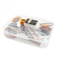
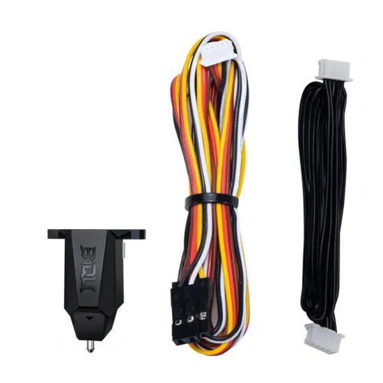
- 1 BIGTREETECH MicroProbe V2.0.
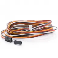
- 1 150mm short cable.
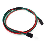
- 1 1000mm extension cable.
- 2 M2.5 × 5mm screws.
- 2 M2.5 × 8mm screws.
- 2 M2.5 nuts.
- 1 user manual.
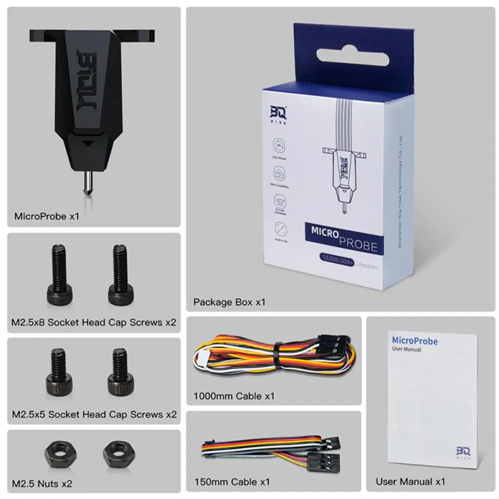
The mounting bracket is not included unless expressly stated in the product options.
Alternative probe technologies
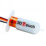
For a BLTouch-type operating system, consider the 5V Fysetc 3DTouch. Voron users looking for a removable magnetic probe may prefer the Fysetc PCB Klicky kit with Omron microswitches.
These alternatives use different mounts, wiring and firmware configurations and must not be interchanged without adapting the machine.