

- Stock: Out of Stock
- Model: Resistencia 24V 70W
Model:

12V 40W

12V 50W

24V 40W

24V 50W

24V 60W

24V 70W

24V 80W
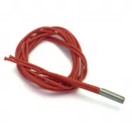
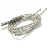
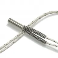
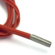
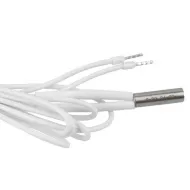
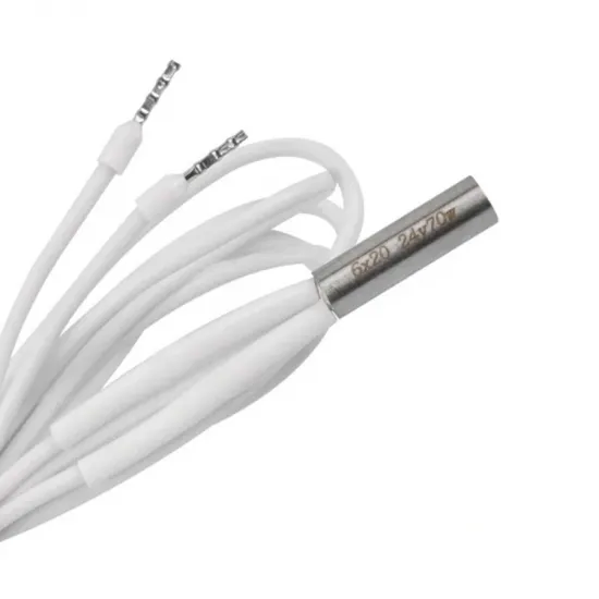
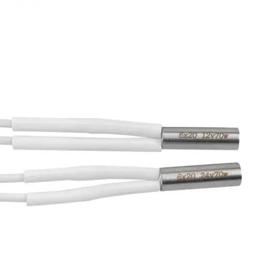
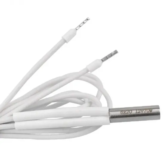
24 V, 70 W heater cartridge for hotend blocks with a cylindrical Ø6 mm bore. This high-power variant is intended for systems that can both use and safely handle it: before replacing a 40 or 60 W heater, check the controller output, power supply, terminals, wiring, sensor, block and thermal configuration.
The 70 W rating may shorten heat-up time and improve temperature recovery in high-flow hotends, but it does not itself increase safe temperature or maximum flow. A more powerful cartridge also reduces electrical headroom and may increase overshoot unless control is properly limited and retuned.
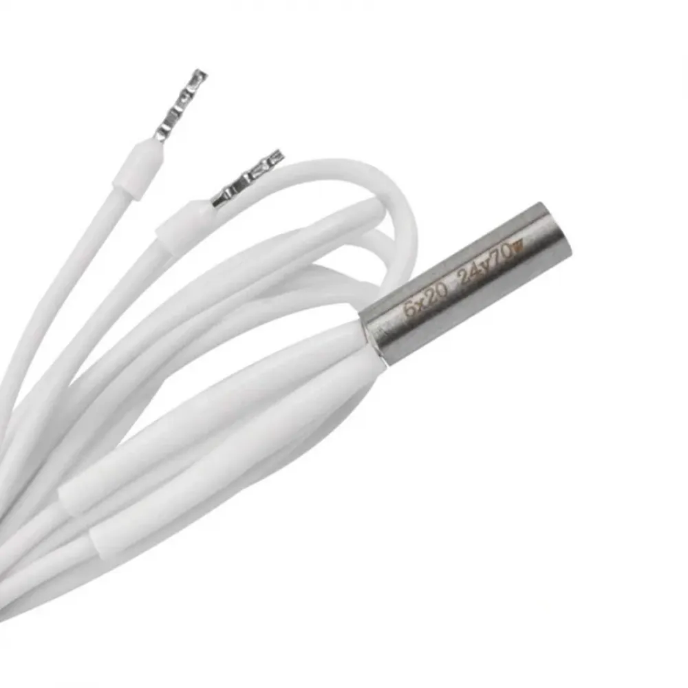
Technical specifications
| Property | Value |
|---|---|
| Rated voltage | 24 V DC |
| Rated power | 70 W |
| Cartridge dimensions | Ø6 × 20 mm |
| Declared sheath material | 304 stainless steel |
| Cable length | 1 m |
| Declared conductor cross-section | 0.653 mm² |
| Declared cable outer diameter | 2.1 mm |
| Calculated rated current | Approximately 2.92 A at 24 V |
| Calculated rated resistance | Approximately 8.23 Ω |
| Advertised cartridge maximum temperature | 470°C; not the safe temperature of the complete hotend |
| Contents | 1 heater cartridge |
The 2.92 A and 8.23 Ω figures are calculated from 24 V and 70 W; they are not individual measurements. Cold resistance may differ due to tolerances, temperature and lead resistance.
Mechanical and electrical compatibility
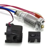
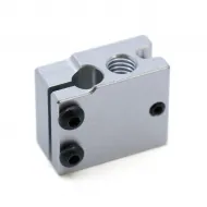
It may be used with blocks featuring a straight Ø6 mm bore with enough usable length for a 20 mm cartridge and a retention system that keeps it fully inserted. It can be dimensionally combined with the V6 heater block for cartridge and thermistor only after confirming the bore and that the complete assembly supports this power level.
The machine must operate at 24 V, and the power supply, MOSFET output, terminal, connector and wiring must continuously handle at least 2.92 A with the margin specified by their manufacturers. A controller accepting a 24 V heater does not necessarily mean its output is rated for 70 W. If the electronics manufacturer does not document sufficient capacity, do not connect it directly.
It is not a direct replacement for flat, ring, clamp-on or integrated ceramic heaters, or for proprietary hotends with another geometry, connector or approved power rating. It must not be connected to 48 V either; with an equivalent resistive load, theoretical power would rise by approximately four times.
Checks before installation
- With the cartridge disconnected, measure resistance between the leads. A value near 8.23 Ω is a useful reference; a major deviation must be investigated before applying power.
- Check that there is no obvious continuity from either lead to the sheath. A multimeter can reveal gross shorts but is not a substitute for a professional insulation-resistance test.
- Verify Ø6 × 20 mm, block depth, retention and cable routing.
- Review the continuous rating of the output and every circuit component. The 70 W version draws approximately 16.7% more current than the 60 W version.
- If the system was designed for lower power, use the controller and hotend documentation to decide whether output must be limited or another cartridge should be selected.
Installation and first start-up
- Work with the machine off, disconnected and cold.
- Fully insert and secure the cartridge without deforming the sheath or pinching the cable.
- Never energise it outside the block.
- Use wiring, terminals and connectors rated for the current and temperature, with suitable strain relief on moving sections.
- Secure the sensor independently and confirm a stable ambient reading before heating.
- Start with a supervised low-temperature test, verify that heating stops, and then perform a new thermal tune.
- Keep insufficient-heating and thermal-runaway protection enabled.
Marlin, Klipper and RepRapFirmware setup
Marlin
Configure the sensor and output correctly, set a safe thermal limit for the whole hotend, and keep THERMAL_PROTECTION_HOTENDS enabled. Under PID, hotend 0 can be tuned with M303 E0 C8 S210 —replacing 210 with a representative safe temperature— and saved with M500. If MPC is used, enter heater power with M306 P70 before running M306 T. Do not use PID and MPC simultaneously.
Full power may be excessive for some assemblies. Under PID it can be limited using PID_MAX; the value must be selected from the output rating, block and measured thermal response, and requires a fresh tune. Do not copy limits or constants from another machine.
Klipper
Check heater_pin, sensor_type, sensor_pin, min_temp and max_temp in [extruder]. Where required, max_power limits output from 0.0 to 1.0. After an initial low-temperature test, run PID_CALIBRATE HEATER=extruder TARGET=210 at a normal operating temperature and save with SAVE_CONFIG. Heater verification is enabled by default; do not weaken it to avoid alarms caused by a real problem.
RepRapFirmware
In RepRapFirmware 3, define the sensor and output first with M308 and M950. The official example for heater 1 is M303 H1 S210; use the correct number and temperature for your configuration. Review the resulting M307 model, including its power limit, and save with M500 where appropriate. Keep thermal monitoring active and do not widen M570 limits to mask an incorrect model, sensor or installation.
Perform any auto-tune under supervision, with the hotend fully assembled, the heatsink fan running and clear space around the toolhead. Stop if temperature rises abnormally, fails to settle, or wiring and terminals become hot.
This product is for you if
- Your 24 V hotend accepts a Ø6 × 20 mm cartridge and is designed for 70 W.
- You need higher thermal recovery and have validated the complete electrical path.
- You can limit, tune and test the heater under controlled conditions.
This product is not for you if
- The controller or hotend only documents lower-power cartridges.
- Your system is 12 or 48 V, or uses a different heater geometry.
- You want to raise maximum temperature without reviewing the sensor, block, heatbreak and firmware.