

In this post we want to explain in a complete, clear and concise way the main aspects to calibrate your 3DSteel and obtain professional results. We will go a little beyond the basic concepts, but we will try to reel it as much as possible so that it does not turn out to be an overly technical reading.
It should be noted that sometimes there are two or more ways to address the same problem and, therefore, different valid solutions, we are going to offer in this article the solution that according to our criteria is best at the date of publication.
This tutorial is designed for our 3DSteel / P3Steel, if you have another printer you can also take it as a reference.
Fuser and Heated Bed PID Calibration
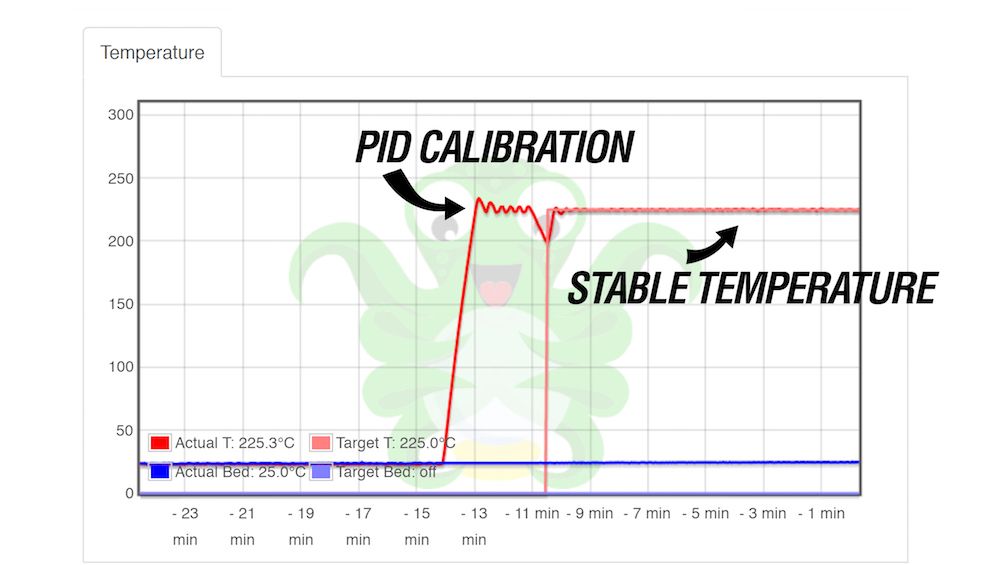
It is something very simple that however frequently raises doubts.
Why do it?
Temperature control by PID is the way we have to keep the temperature as stable as possible during printing, since temperature fluctuations can cause us:
- Changes in the color of the printed part.
- Vertical marks in the print, especially evident if you use a powerful and light bed like the bed of our 3DSteel V2, and not so evident if you use glass or another element with great thermal inertia, as well as heavier and less powerful beds like the Mk3.
- Error messages in Marlin, in rare cases.
We send standard values in our kits that are valid in most situations, but these values are sensitive to:
- Room temperature.
- Air currents.
- Small differences between elements, such as wearing or not wearing a thermal sock, using an aluminum or brass block, etc.
How to do it?
It is extremely simple from the LCD, we go to the following route:
- Setting
- Advanced configuration
- Temperature
- There we find the PID of the fuser 1 and the PID of the heated bed.
We just have to click and wait for the process to be done automatically. Once done, save memory from the LCD itself.
You may have seen that the calibration temperature can be selected, since it is not the same to print at 180ºC than at 280ºC, the calibration values will not be the same either, we recommend selecting a temperature close to the printing values of the filament you use the most.
During printing the temperatures remain very stable, if not, the process must be repeated.
Steps / mm calibration
The X, Y, and Z axes are calibrated with their mathematical formula based on the mechanical components and controller settings, 80, 80, 400 for our factory configured 3DSteels.
There are those who advise printing a test piece and adjusting the steps per mm to compensate for the thermal contraction of the material, but this from our point of view is a mistake, since it is something typical of the material not of the machine, there are other ways better to compensate for this:
- Compensate in design, giving tolerances that consider that the piece will contract especially in X and Y. For example, we can make an 8m hole have a nominal measurement of 8.1 if we want an 8mm component to fit inside, or 8mm if we want it to tighten.
- Use features from cutting programs such as "XY Size Compensation" for parts that need to fit precisely.
In any case, the thermal contraction is something that we recommend not to link with the steps per mm of the 3D printer.
Steps per mm in the extruder
It is perhaps the most well-known calibration of all, when we want the filament to advance 1mm, we want it to advance exactly 1mm, not 0.9mm or 1.1mm, also when we want it to deposit 1mm3 of material, we want it to deposit exactly that amount of material. It is something obvious that it may seem simple, but in practice it is much more complicated than it seems. Iin fact, you may have already noticed that we have mentioned the filament that enters and the filament that deposits using two different units, and that is there is a large variable between the two units, the filament diameter, which is not always constant.
¿Como podemos entonces calibrar un extrusor si el diámetro del filamento no es siempre constante?
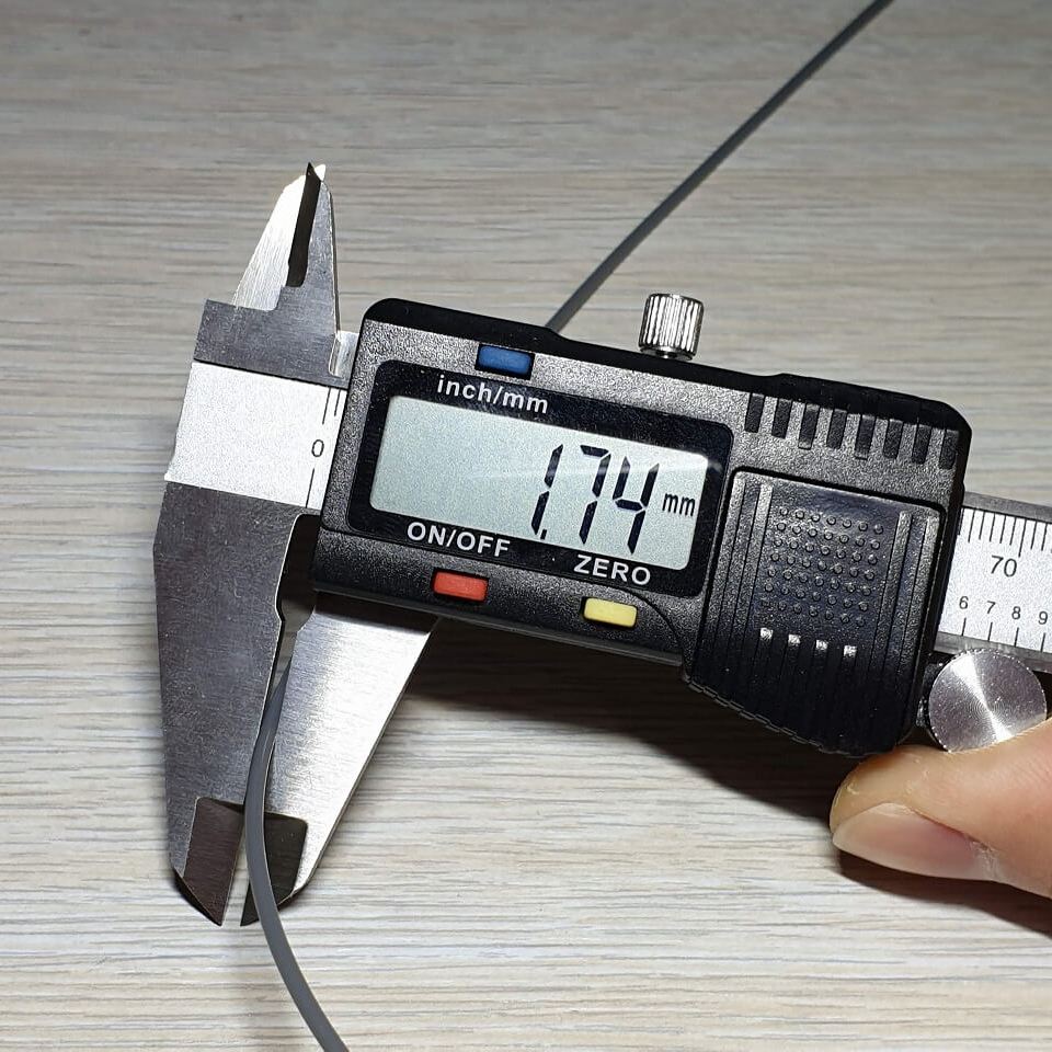
Existen varias formas, nosotros recomendamos calibrar simplemente el material depositado, considerando todo el material como 1,75mm aunque no lo sea. Normalmente oscila entre 1.72 y 1.78.
How to accurately measure the deposited material?
We recommend two different impressions, obtaining a value that gives us good results in both:
- Hollow cube.
- Solid top cube.
The hollow cube will be printed as follows:
- Intermediate layer height, for a 0.4 nozzle a 0.2 layer height is correct.
- 1 single outer perimeter.
- 0% infill.
- 2 or 3 solid layers at the base and 0 at the top.
- Known extrusion width and better a round number, for example 0.5
Once the cube is printed, measure with a caliper in the center of each of the four faces to calculate its average.
We make a simple equation:
"Number of calibrated steps" = "original number of steps" * (expected thickness / thickness obtained in measurement)
For example:
NCS = 130 * (0.5/0.52) = 125
It would be enough to lower the steps per mm to 125 to obtain an accurate extrusion.
This check must be done periodically since there could be variations between one coil or another, and between different materials.
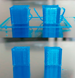
The cube with a solid top is a visual assessment, it simulates a piece printed with these values and does not confirm whether the value obtained is valid or not, it is very simple to do it frequently, since it does not need a gauge, it is visually checked.
To do this test we print a cube similar to the previous one, but with these values:
- Intermediate layer height, for a 0.4 nozzle a 0.2 layer height is correct.
- 2 or 3 outer perimeters
- 10% filling.
- 2 or 3 solid layers at the base and 10 at the top.
- Extrusion width similar to the one we use in the parts we want to print.
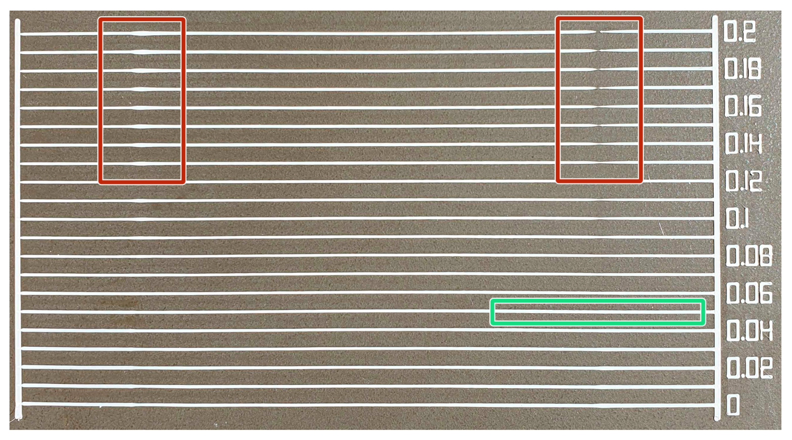
On the upper face we must obtain a pattern in which the lines remain parallel without overlapping, if there is a gap between them, the extrusion is less than desired, if they overlap, it is excessive. It is common in this case that there are areas with small excesses and other areas with small deficiencies, this would also be a correct calibration that we will correct in the next point.
K factor calibration for linear advance
We are including this function active in our printers from version 2.0.7.2. Its calibration is very simple and offers us a very significant improvement in print quality, since it improves extrusion changes in a surprising way, the edges, areas of sudden change of direction, the union between the filling and the perimeters, will remain much better with this function.
To do this, we have to:
- Calculate the K factor for a certain material.
- Insert it into the printer.
To calculate the K factor we can use this tool that Marlin offers us:
https://marlinfw.org/tools/lin_advance/k-factor.html
Or download our Gcode already prepared.
We can see when printing parallel lines, with two key points:
- Acceleration zone, where without this factor, material is lacking.
- Braking zone, where without this factor there is plenty of material.
The first line that is uniform will be the correct measurement, for PLA in our extruder we obtain values below 0.1. The factors involved in this result are:
- Material flexibility, the more flexible the value, the greater the value, and may be excessive with very flexible materials, in which case it is better to set it to 0 and use a constant and low speed during printing.
- Nozzle and maintenance status, the wider, newer and cleaner the nozzle is, the better and lower this value will be.
- Extruder type, very precise direct extruders like ours will give low values, bowden extruders with little control over extrusion will give high values difficult to control.
Once we have calculated this value we can enter it in two ways:
- Using the Gcode M900 S [obtained value], for example M900 S0.08
- This gcode can be linked to the material profile, so you can have for example 0.08 for PLA and 0.1 for PETG.
- From the LCD to "Prepare" while the printer is printing. You can also save memory.
Retraction
We recommend calibrating this parameter last, since it will give us a different value depending on whether we have correctly calibrated the K factor or not.
In the latest versions of Marlin we can control the retraction from the LCD, in the configuration / retraction menu or in the Gcode, for this in Slic3r you can select "Printer Settings / General / Advanced / Use firmware Retraction" by checking the box, in this way We will use the retractions of the LCD and we will be able to do all the tests with the same Gcode.
To do the test we have to make several printings with different retraction lengths until we obtain the minimum value in which there are no "threads" in the center of the piece, the value that we will obtain will be less than 1mm, so we can try with:
- 0.5mm
If there are threads left or not we can go up or down 0.2mm, to test for example 0.3 or 0.7mm. We will repeat this system a couple of times until we find the minimum value that leaves us clean printings.
This value can change from one material to another, with different print settings such as layer heights or speeds, as well as with the state of maintenance of the nozzle.
Additional considerations:
- With this way of calibrating the printer we avoid the need to use "smart" functions of programs like Cura, since they would be redundant, functions like "Coasting" in Cura or "Presure advance" in Slic3r.
Have you come this far? If you have done the calibrations that we indicate in this post, you are surely printing with great results, if this is the case we invite you to publish it on social networks and tag us.
If you have arrived and have any questions or comments, you can leave it at the bottom of the blog to help other readers, or ask us directly using the contact form so that we can help you get the most out of your 3DSteel.
Related Products


1 Comment(s)
Where can we find: "Or download our Gcode already prepared." for K-factor calibration ?
Please try again, link solved now:https://drive.google.com/file/d/1LRj4g5Zg8o8BjQ_pwm41Y03IJk4tw6Z2/view?usp=sharing
Leave a Comment