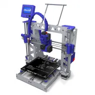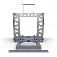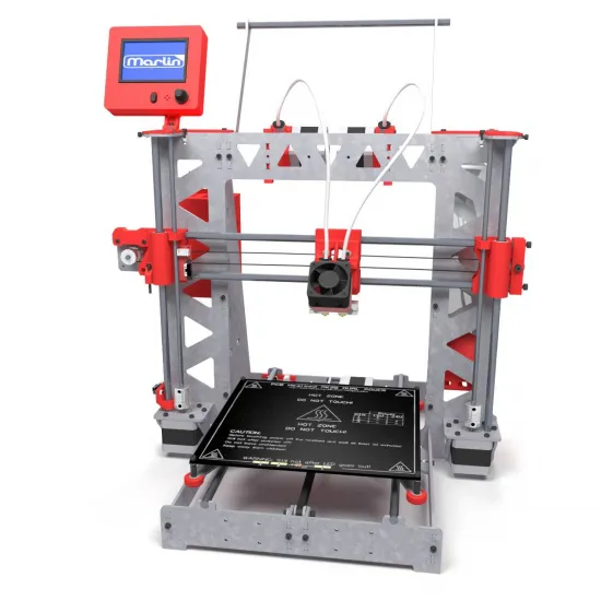
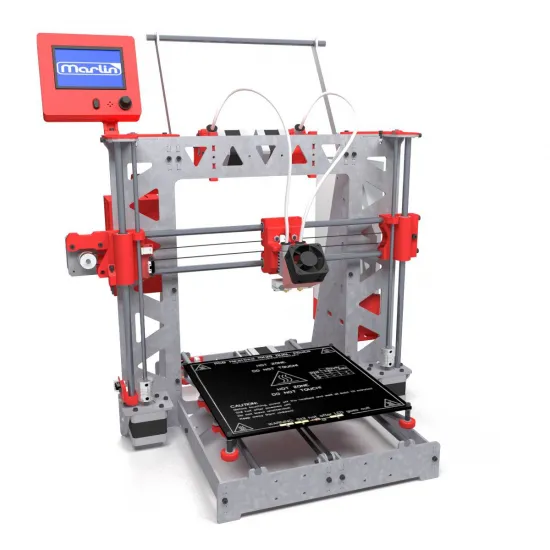

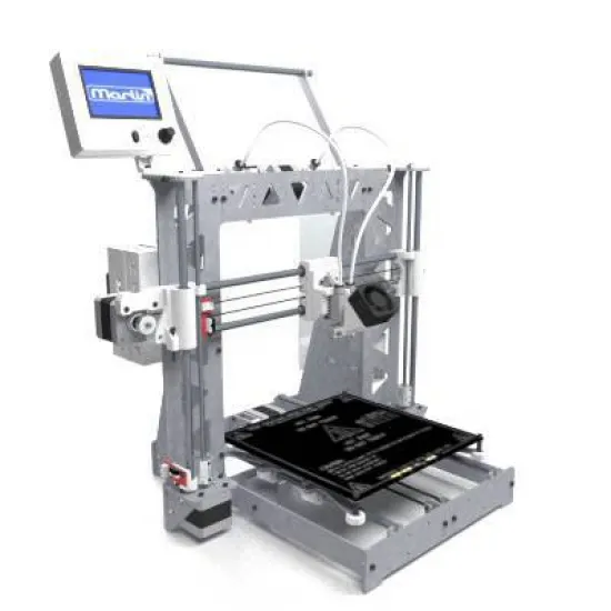
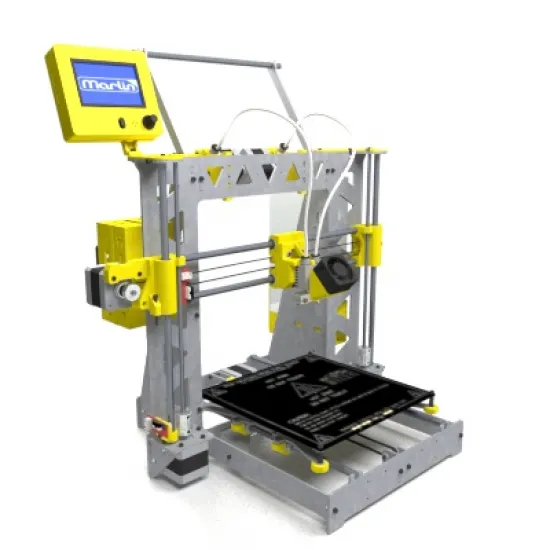
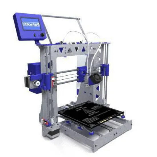
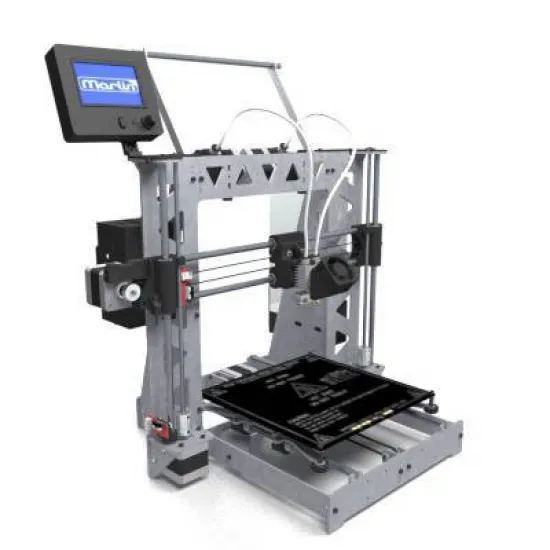
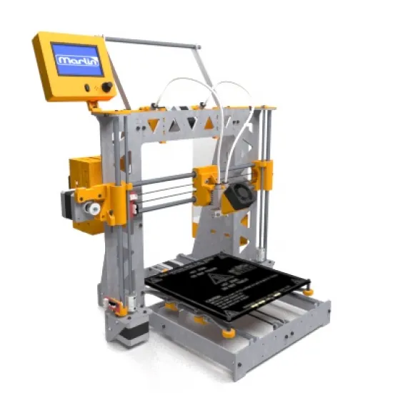
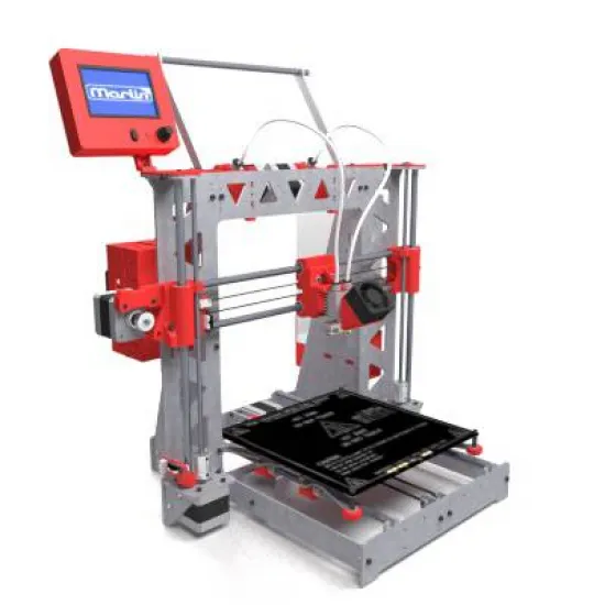


The HTA3D P3STEEL DUAL is a steel-frame DIY 3D printer kit with dual Bowden extrusion, developed by HTA3D during the 2016-2017 generation. It is based on the open P3Steel/RepRap architecture and is intended for users who enjoy building, understanding, tuning and maintaining their own machine.
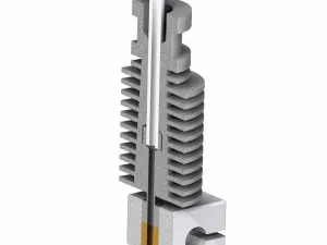
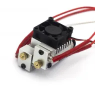
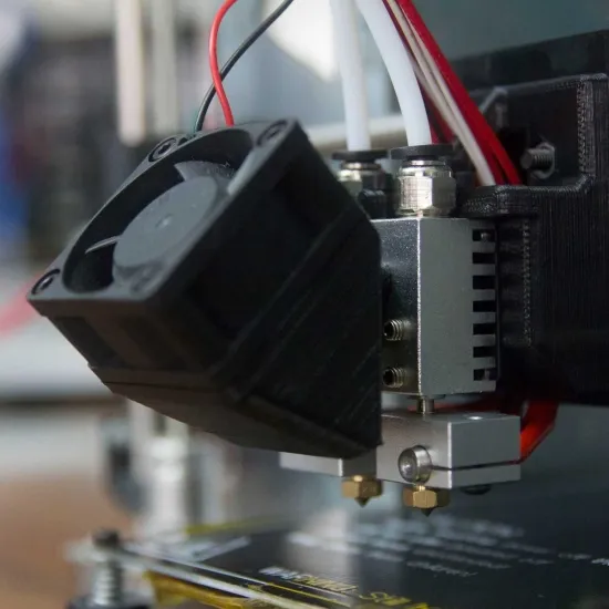
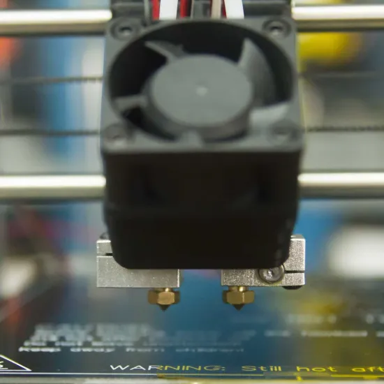
Its two MK8 extruders feed a hotend with two fixed, independent nozzles. This arrangement can print in two colours, combine a primary material with a support material, or dedicate each tool to a different task, provided that both materials have mutually compatible printing requirements.
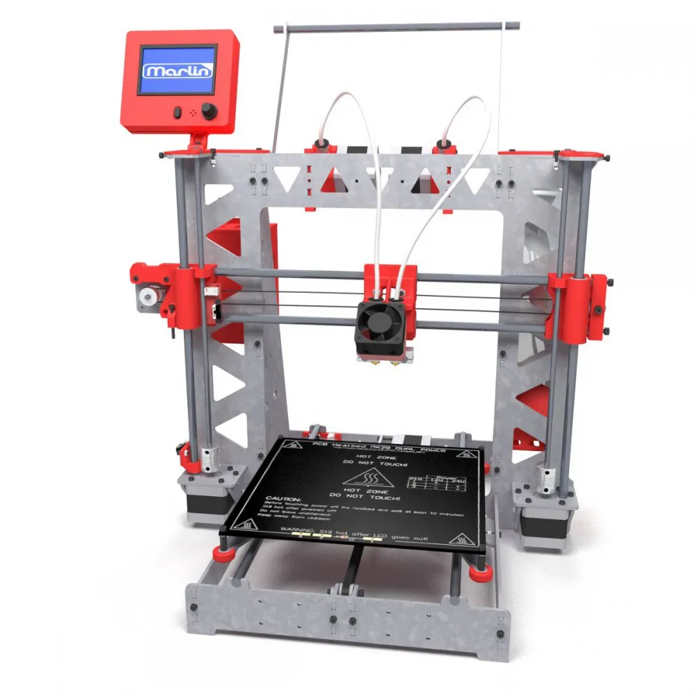
Main specifications
| Feature | Documented configuration |
|---|---|
| Build volume | 200 x 200 x 200 mm (X/Y/Z). |
| Frame | 3 mm steel frame, available in galvanised steel or 304 stainless steel. |
| Kinematics | Moving-bed Cartesian; GT2 belts on X/Y and M5 or T8x8 on Z depending on the option. |
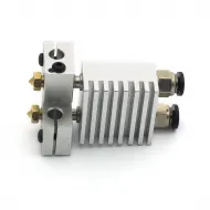
| Extrusion | 2 MK8 Bowden extruders for 1.75 mm filament and a Chimera-style hotend with 2 fixed nozzles. |
| Selectable nozzles | 0.30, 0.35, 0.40 or 0.50 mm for each tool. |
| Electronics | Mega 2560-compatible controller, selectable RAMPS, 5 DRV8825 drivers and 12864 LCD with SD reader. |
| Power | 12 V system with a documented 30/33 A power supply. |
| External size | Approximately 47 x 38 x 60 cm with holder and standard spool, plus free space in front and behind for bed travel. |
| Weight | Approximately 12 kg in a basic configuration; frame and options affect the final value. |
A customisable kit
The printer is prepared for the selected combination. The product selector allows the frame, Z drive, hotend, nozzles, bed and linear motion to be adapted. The configuration shown in the order takes precedence over photographs or documents from earlier revisions.
| Group | Current options | What changes |
|---|---|---|
| Frame | Galvanised steel or 304 stainless steel. | Finish, environmental resistance and final weight. |
| Z axis | Original M5, T8x8 with couplers or motors with integrated 310 mm T8x8 screws. | Parts, couplers and firmware steps per millimetre. Profiles must not be interchanged. |
| Heatbreaks | PTFE-lined, combined PTFE/all-metal, all-metal, titanium or bimetal depending on availability. | Thermal range, heat transfer and behaviour with each material. |
| Heated bed | MK2B or aluminium MK3, including a 220 x 220 mm version. | Construction, thermal inertia and the surface supporting the build plate. |
| RAMPS | 1.4, 1.5 or 1.6+. | Physical revision; identify the installed board before repairs or firmware updates. |
| Linear motion | LM8UU, mixed Igus/LM8UU or Igus DryLin. | Friction, sound and fit. Do not combine tolerances without checking free movement. |
How dual extrusion works
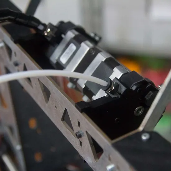
Both NEMA 17 motors and their MK8 mechanisms are mounted on the frame. Each drive pushes filament through a PTFE tube into an independent hotend channel. The X carriage carries the shared heatsink, two heating zones and two nozzles. Keeping the motors off the carriage reduces moving mass compared with a dual direct-drive arrangement.
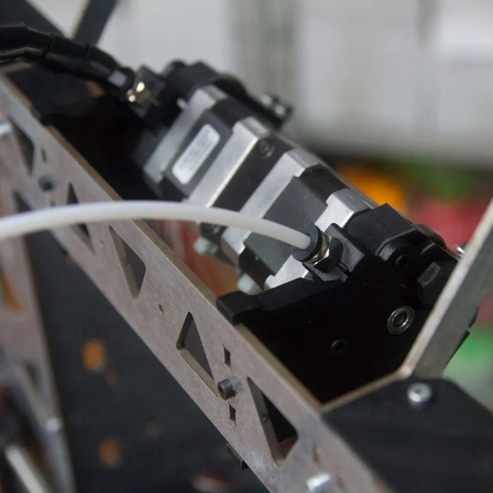
Both nozzles always move together. The inactive tool remains close to the model, so nozzle heights must be aligned accurately and the slicer must manage ooze with standby temperature, retraction, priming, a purge tower or an ooze shield when required.
Kit contents
The kit groups the modules required to build the printer in the selected configuration. Exact references may change with the selected options and stock evolution.
| Module | Main documented components |
|---|---|
| Structure | Main frame, sides, braces, front/rear Y plates, metal brackets, lightened Y carriage and upper spool support. |
| Guides and transmission | Six 8 mm smooth rods, selected Z transmission, 12 linear bearings/bushings, F624ZZ, MR105ZZ, 608ZZ, GT2 belt, 20-tooth pulleys and couplers where required. |
| Extrusion | Two MK8 extruders, dual hotend, two heaters, two sensors, two nozzles, PTFE tubes, fittings, 3010 heatsink fan and 4020 part-cooling fan. |
| Electronics | Mega 2560-compatible controller, selected RAMPS, five DRV8825 drivers, auxiliary MOSFET module, six motors, three endstops, 12864 LCD and wiring. |
| Bed | Selected heated bed, thermistor, insulation, wiring, four springs and levelling parts. |
| Power | 12 V power supply, switch, mains lead, terminals and printed connection cover. |
| Finishing and assembly | Printed parts, dedicated fasteners, Kapton tape, heat-shrink tubing, spiral wrap and cable ties. |
For repairs or partial projects, HTA3D also offers the P3Steel Dual printed-parts kit, the dedicated P3Steel Dual fastener kit and the complete HTA3D dual Bowden extruder.
Hotend, nozzles and materials
Each nozzle can currently be selected from 0.30 to 0.50 mm. Using the same diameter for both tools simplifies line-width and layer-height setup for an initial dual-material configuration. Different diameters require tool-specific slicer settings.
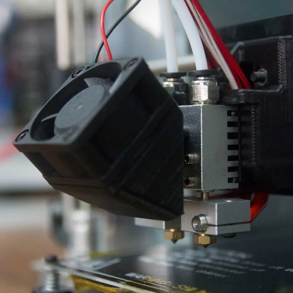
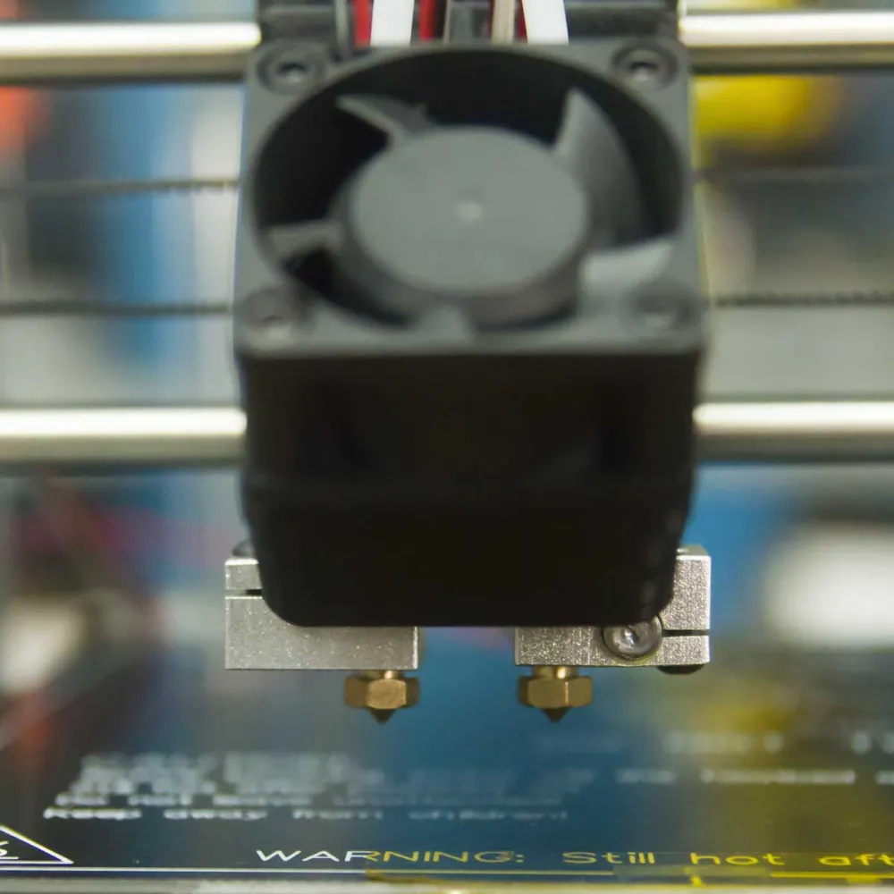
Material compatibility depends on the selected heatbreak, actual safe temperature, heated bed, build surface and the printer's open environment:
- PTFE-lined heatbreaks: provide a guided path, but HTA3D historically limits this configuration to 245 °C. Never exceed the rating of the installed tube.
- All-metal, titanium or bimetal: remove PTFE from the hot zone and may suit higher-temperature materials, but they do not automatically make the whole printer a 300 °C system.
- Engineering materials: ABS, ASA, nylon or PC may require drying, a dedicated surface, environmental control or an enclosure. If an enclosure is added, keep electronics and the power supply within their safe temperatures.
- Flexible materials: Bowden performance depends on hardness, filament confinement, tube length and extruder adjustment; very soft TPU is not universally compatible.
- Dual materials: both filaments must also be reasonably compatible in adhesion, shrinkage and layer height.
The 4 x 2 mm PTFE tube is the format used for 1.75 mm filament. The 18 mm Chimera-style dual heatsink belongs to the same family, but thread, spacing and mounting geometry must be compared with the installed hotend before replacement.
Marlin configuration
The original platform uses Mega 2560, RAMPS, five DRV8825 drivers and Marlin. The kit is supplied with firmware loaded and drivers adjusted for the selected combination. The page also retains historical Marlin 1.1.x files and a 2.x repository; do not flash an old archive without first identifying the physical revision.
- Select the exact dual-extrusion profile and the installed Z drive: M5, coupled T8x8 or integrated T8x8.
- Set
EXTRUDERS 2and use a RAMPS mapping with two hotends and one bed that matches the selected board; conventional RAMPS builds normally use the EEB arrangement. - Do not enable
DUAL_X_CARRIAGE,SWITCHING_EXTRUDERorSWITCHING_NOZZLE. - Set
TEMP_SENSOR_0,TEMP_SENSOR_1andTEMP_SENSOR_BEDfor the actual sensors. The documented bed uses a 100K B3950 NTC and normally matches table 11 with a 4.7 kΩ pull-up; do not automatically apply that table to both hotends. - Calibrate E0/E1 steps and each hotend PID independently. Retune the bed PID if its thermal assembly changes.
- Measure the second nozzle offset and set it with
M218 T1 X... Y.... Check withM503and save withM500when EEPROM is enabled. - Keep thermal protection enabled. The shared heatsink fan must run whenever either hotend is hot.
The documented 18 mm X and 0 mm Y values are only a historical starting point. Measure the final offset and repeat calibration after changing a nozzle, heatbreak, block or heatsink.
Can it use Klipper?
Yes. Mega 2560/RAMPS can operate as a Klipper MCU, but this is an advanced conversion rather than a ready-to-copy setup. It requires a host, flashing the controller and creating a printer.cfg for the actual revision and wiring.
The configuration requires independent [extruder] and [extruder1] sections, plus the bed, fans and endstops. T0/T1 macros must activate the correct tool and apply the measured offset. Pins, rotation_distance, PID values and thermal limits are not universal and must be derived from the installed board and calibrated machine.
Assembly and documentation
HTA3D published an illustrated series covering the frame and Y axis, both M5 and T8 Z variants, bed, dual extruder, power supply, electronics, commissioning, flow calibration and nozzle offset. This remains especially useful when maintaining or rebuilding a unit years after purchase.
- Frame and Y-axis assembly.
- Dual-extruder assembly.
- Dual electronics and wiring.
- Nozzle-offset calibration.
The tutorials depict the original machine and may show parts or methods from an earlier batch. Always check the received options and contact HTA3D before changing power wiring or flashing firmware.
Safe commissioning
- With power disconnected, identify the RAMPS revision and check driver orientation, mains selector, 12 V polarity, terminals and protective earth.
- Power on first to check the LCD and fans without commanding full-axis movement.
- Heat each hotend to a low test temperature and confirm that only its paired sensor rises. Repeat for the second hotend and then the bed.
- Check X, Y and Z direction separately and trigger each endstop manually before running a complete homing cycle.
- Level both sides of Z, level the bed and align both nozzles to the same height.
- Calibrate E0/E1, flow, PID and X/Y offset, then tune retraction, priming and standby temperatures for each material.
It is for you if...
- You want an open DIY kit that can be built, repaired and modified.
- You want two-colour or model/support printing through two independent nozzles.
- You value a steel frame and extensive assembly documentation.
- You want to understand and calibrate mechanics, electronics and firmware instead of relying on a closed system.
- You are maintaining or rebuilding an existing P3Steel Dual with parts from the same family.
It is not for you if...
- You want a modern ready-to-use printer with automatic levelling, networking, automatic profiles and little maintenance.
- You need high speed, a factory enclosure or controlled chamber temperature.
- You require IDEX, duplication, mirror mode or a mixing nozzle.
- You do not need two materials and prefer the simplicity of a single hotend; the single-extrusion HTA3D P3STEEL may be a better fit.
- You prefer a later HTA3D platform with 24 V power and 32-bit electronics; consider the 3DSteel V2.
Assembly Tutorial
New step by step tutorials:
We have prepared a new updated tutorial serie, with further information about available options. Also printable, so you don't need a display to follow the instructions:
Assembly Tutorial (Spanish with English subtitles):
Important: We recommend reading the instructions in this tab completely, in addition to following the assembly from here since we have included additional information to the videos.
Updates:
- Thermistors have now dupont connector, no soldering required.
- Stepper motors include cable connector on base. In addition, we ship them with the wires in the correct order for Ramps 1.4. So you do not have to change the order.
- Marlin updated to 1.1.0 RC 7 version:
- Improved filament change system from the LCD or using command M600
- Bed leveling function optimized, get easily a perfect first layer.
- Small bugs fixed, now more information is displayed on the LCD.
Frequently asked questions:
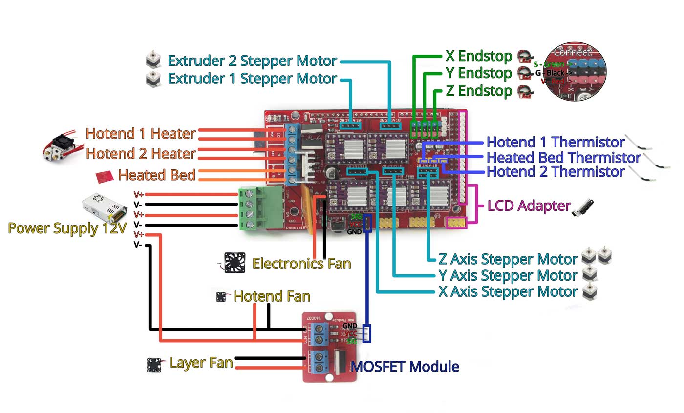
- How all fans are connected to the printer?
Fans are connected as follows:- Layer fan: connected to MOSFET module as indicated in the video
- Hotend fan: connected directly to 12V through the feeding of the module MOSFET as indicated in the video. This connection can be done as well connected to directly to the Power Supply.
- Electronics Fan: connected directly to the output of 12V in RAMPS (the connection we find down the X axis stepper driver) as shown on video. This connection can be done as well connected to directly to the Power Supply.
- The extruder motor does not move when I try to move it from the LCD.
Marlin has a protection to prevent accidental movement, so the extruder will not move with temperatures under 170°C. Try heating the hotend over this temperature and the extruder will move
Assembly drawings:
Xmotor, Leadscrews version:
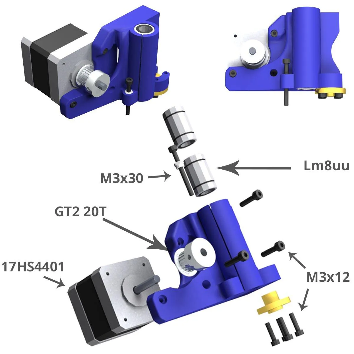
X idler, Leadscrews version:
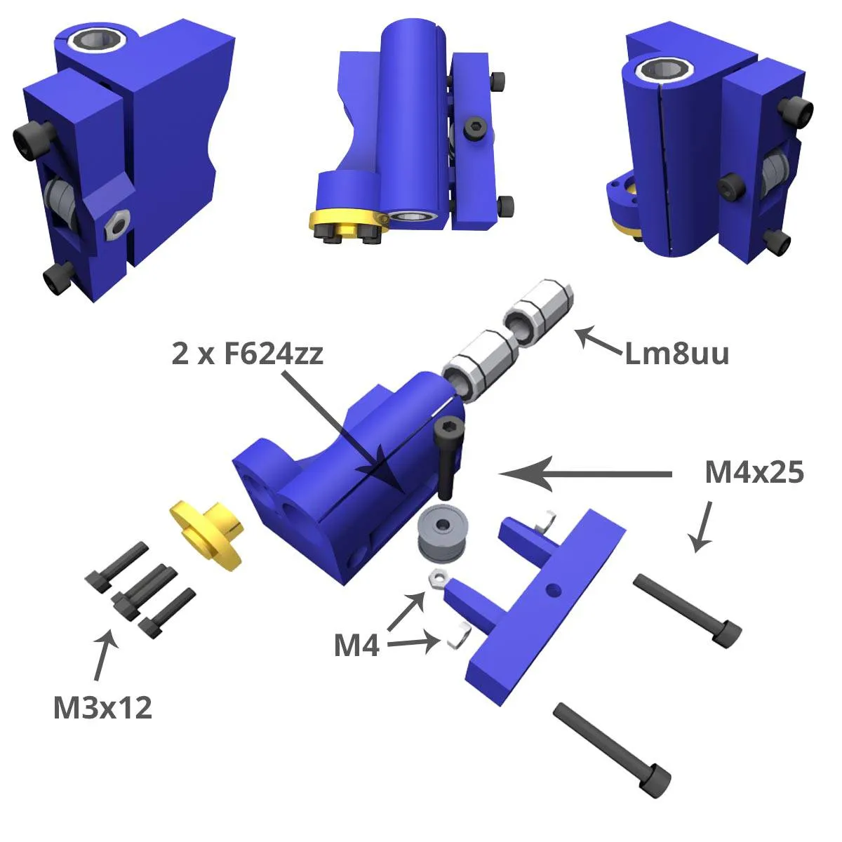
Connection Diagram of RAMPS 1.4:
Order and Orientation of the Stepper Motor wires:
-
Keep the colour order of the wire; the RED wire goes DOWNWARDS when connecting to the RAMPS.
Additional considerations:
- Connect limit switches as indicated in the video or scheme, an incorrect connection can damage the Mega board.