

- Stock: 90
- Model: TMC2130-SPI-Fysetc

Model:

TMC2208

TMC2130

TMC2209
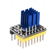
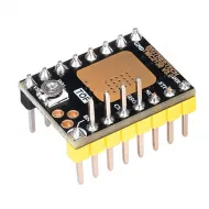
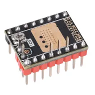
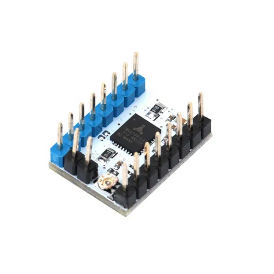
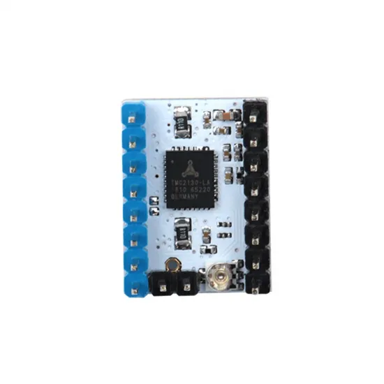
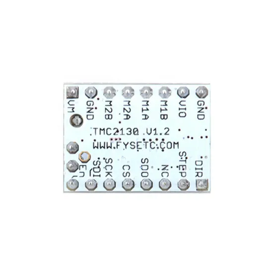
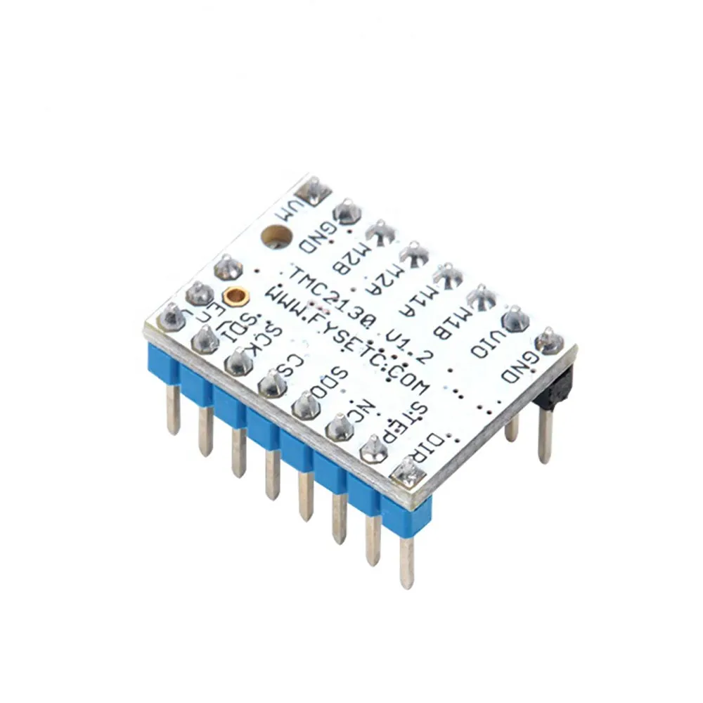
The FYSETC TMC2130 V1.2 is a bipolar stepper motor driver prepared for SPI operation. In addition to STEP and DIR motion signals, firmware can configure current, microsteps and operating mode, read diagnostics and use StallGuard2 when the controller board also routes the required signals correctly.
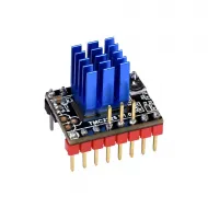
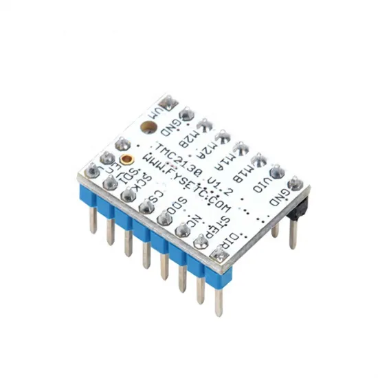
FYSETC designed this V1.2 revision with SPI and DIAG connections on the underside for its F6 board. It may be used with other controller boards that document a compatible socket and routing, but it is not a universal replacement merely because it follows the StepStick format. For a simpler installation without SPI, see the BIGTREETECH TMC2130 V3.0 STEP/DIR.
What SPI enables
- Set RMS current from Marlin or Klipper.
- Select microsteps and interpolation through firmware.
- Choose between StealthChop for reduced noise and SpreadCycle for more dynamic operation.
- Read temperature, short-circuit, open-load and other driver states.
- Use CoolStep and StallGuard2 load measurement when explicitly configured.
- Implement sensorless homing when the board routes DIAG or supports the required status reading and the mechanism can be calibrated reliably.
These features do not become active merely by inserting the module: the controller board must route SPI, provide a separate CS for each driver and use firmware configured for its exact pinout.
Technical specifications
| Feature | Value or condition |
|---|---|
| Manufacturer and revision | FYSETC TMC2130 V1.2 |
| Driver IC | Trinamic TMC2130-LA, two-phase bipolar motor |
| Interface | STEP/DIR for motion and SPI for configuration/diagnostics |
| Stated VM range | 5.5-46 V; 12/24 V recommended for typical use and always limited by the controller board and every component |
| VIO logic voltage | 3-5 V |
| Published maximum current | 1.2 A RMS for the module; 2.5 A IC peak, not a continuous operating current |
| Rsense | 0.11 Ω |
| Microsteps | Up to 256, configurable through SPI |
| Nominal format | StepStick, approximately 20.32 × 15.24 mm |
| Contents | 1 driver and 1 heatsink |
Signals and functional pinout
| Signal | Function | Required check |
|---|---|---|
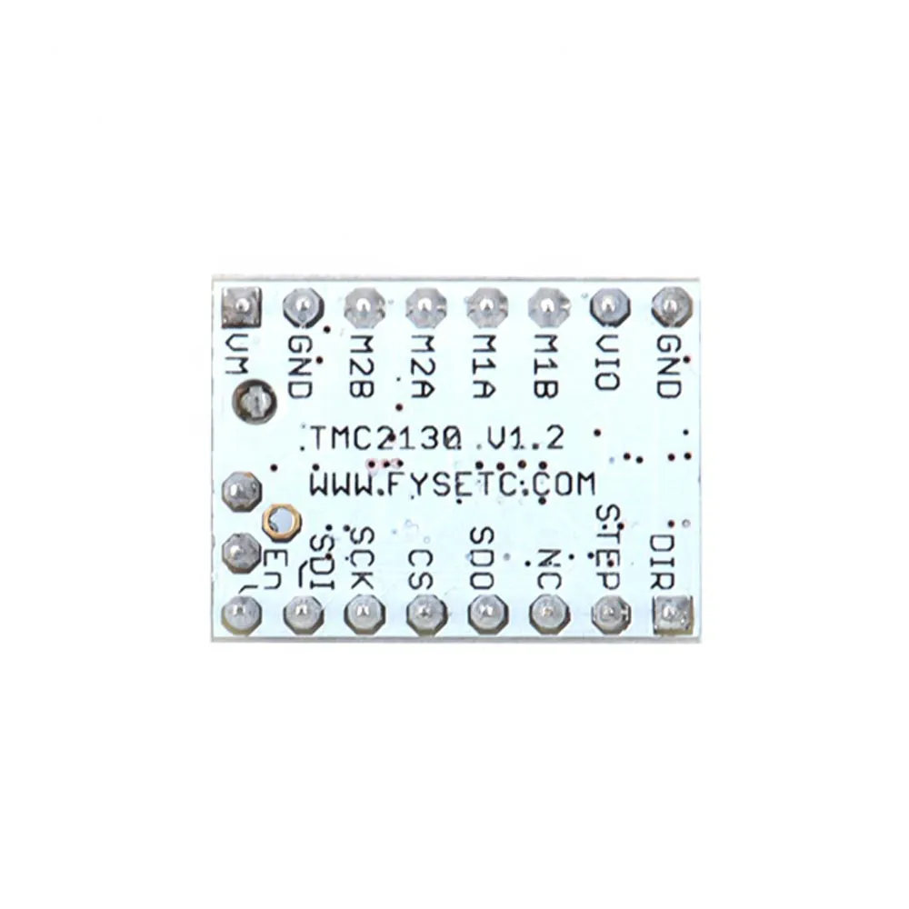
VM / VIO / GND | Motor power, logic power and ground | Exact voltage, position and orientation |
M1A/M1B, M2A/M2B | Two motor coils | Identify each pair before applying power |
STEP / DIR / EN | Motion, direction and enable | Polarity and pins for the controller board |
SDI | Data into the driver; MOSI on the board | Correct SPI bus |
SDO | Data from the driver; MISO on the board | Continuity and shared bus pin |
SCK | SPI clock | Hardware or software SPI pin |
CS | Individual driver selection | One correct CS per axis |
DIAG | Diagnostics and possible virtual endstop | Board routing, polarity and firmware |
Actual compatibility
| System | Compatibility level | Conditions |
|---|---|---|
| FYSETC F6 | Documented by FYSETC | Set the TMC2130 jumpers and firmware for SPI; use DIAG only when sensorless is required. |
| Boards with a TMC2130 SPI socket | Conditionally compatible | VM/GND, VIO, coils, STEP/DIR/EN, SDI/SDO/SCK, CS and, when used, DIAG must all match. |
| A4988/DRV8825 socket without SPI | Not recommended for this version | The TMC2130 V1.2 needs SPI communication for the configuration intended by FYSETC. |
| Board with soldered drivers | Not compatible | Unless an external driver interface is explicitly documented. |
| Two-phase bipolar motor | Current-dependent | Required current must remain within the module's safe thermal range. |
We do not guarantee direct connection to a specific controller merely because it supports “TMC2130” or uses StepStick sockets. Some boards use different auxiliary pins, jumpers, buses or CS positions across revisions.
Current, Vref and cooling
With SPI, Marlin or Klipper programs the operating current, but the FYSETC V1.2 also has a potentiometer and a documented Vref relationship. With its 0.11 Ω sense resistors, FYSETC states:
Irms = Vref × 0.71
Vref = Irms × 1.41
Current is per phase in RMS amperes. Do not copy a value from another printer: begin with the motor specification and include thermal margin. To measure Vref, FYSETC instructs users to power the board from its main supply, disconnect the motor and measure between GND and the potentiometer wiper. Prevent the probe from shorting nearby components.
The heatsink must sit correctly without touching pins and the enclosure must exchange air. If skipped steps, thermal warnings or excessive temperature occur, do not automatically increase current: first inspect mechanics, acceleration, wiring and cooling.
Marlin configuration
In Configuration.h, select TMC2130 —without the _STANDALONE suffix— for each SPI-connected axis:
#define X_DRIVER_TYPE TMC2130In Configuration_adv.h, set the following for each axis:
X_CURRENT: movement current in mA RMS, selected for the actual motor.X_MICROSTEPS: usually 16 as a starting point, with optional interpolation.X_RSENSE 0.11: the value for this carrier.X_CS_PINand SPI bus: use the board definitions or declare the correct pins.STEALTHCHOP_XY,STEALTHCHOP_ZorSTEALTHCHOP_E: enable only on axes where appropriate.
After compiling, run M122 before testing long movements. Responses that are entirely LOW or HIGH indicate an SPI communication fault. Do not proceed until CS, SCK, SDI/MOSI, SDO/MISO, power and orientation have been corrected.
Klipper configuration
Add a TMC2130 section associated with the stepper. This is a template: replace the names with the pins and current for your board and motor.
[tmc2130 stepper_x]
cs_pin: BOARD_CS_PIN
spi_bus: BOARD_SPI_BUS
run_current: MOTOR_RMS_CURRENT
sense_resistor: 0.110
interpolate: True
stealthchop_threshold: 0
If the board does not use a hardware SPI bus, Klipper can define spi_software_sclk_pin, spi_software_mosi_pin and spi_software_miso_pin. Do not mix both methods unless the controller's official configuration calls for it.
stealthchop_threshold: 0 keeps SpreadCycle enabled. StealthChop can reduce noise, but it also changes motor behaviour and should not be enabled indiscriminately on fast axes or those requiring maximum torque margin. Check communication with DUMP_TMC STEPPER=stepper_x before calibrating additional functions.
Sensorless homing: a capability, not a guarantee
StallGuard2 estimates motor load and can be used as a virtual endstop, but it requires SPI, access to DIAG or a supported status-reading method, and calibration on the actual machine. Detection changes with speed, current, motor temperature, friction, belt tension and moving mass.
- First verify motion, direction and physical endstops at a conservative current.
- Calibrate one axis at a time and retain a way to stop the machine.
- Never copy sensitivity from another printer.
- Sensorless is generally more natural on X/Y; it is not a universal recipe for Z or bed probing.
- Recheck sensitivity after changing mechanics, current or operating temperature.
This is for you if
- Your board documents electrical and SPI compatibility with the TMC2130 V1.2.
- You want to configure current, microsteps and modes from Marlin or Klipper.
- You need driver diagnostics or want to experiment with StallGuard2 and CoolStep.
- You can inspect pinout, jumpers, CS and firmware before applying power.
This is not for you if
- You want a driver that can simply be inserted into any A4988 socket.
- You do not want to compile Marlin or edit Klipper's SPI configuration.
- Your board does not expose CS, SPI or a pinout compatible with this revision.
- You only need simple STEP/DIR operation: the standalone version avoids unnecessary complexity.
Safe installation
- Disconnect the power supply and USB; allow capacitors to discharge.
- Set the controller jumpers according to its manual for TMC2130 SPI.
- Compare every signal and orient the carrier using VM/GND and EN/DIR, never by colour.
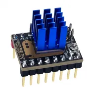
- Install the heatsink without electrically bridging pins or components.
- Connect each motor coil to its corresponding pair.
- Set conservative current, microsteps, CS and SPI before the first movement.
- Power up without commanding motion and verify communication using
M122orDUMP_TMC. - Test short moves, endstops and direction, then monitor temperature during an extended test.
Never connect or disconnect the motor while the driver is powered. Inductive energy can damage the module even when the axis is stationary.
Package contents
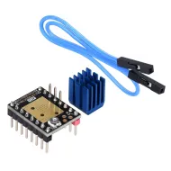
- 1 × FYSETC TMC2130 V1.2 prepared for SPI.
- 1 × Heatsink.
Technical documentation
Refer to the official FYSETC TMC2130 documentation, the official Marlin Trinamic driver guide, the M122 diagnostics page and the official Klipper TMC2130 reference. The controller board manual takes precedence for pins, jumpers and SPI bus selection.