

- Stock: 10
- Model: IO2CAN

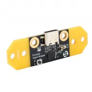
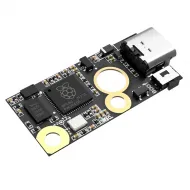
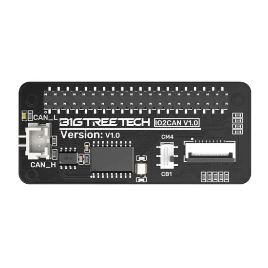
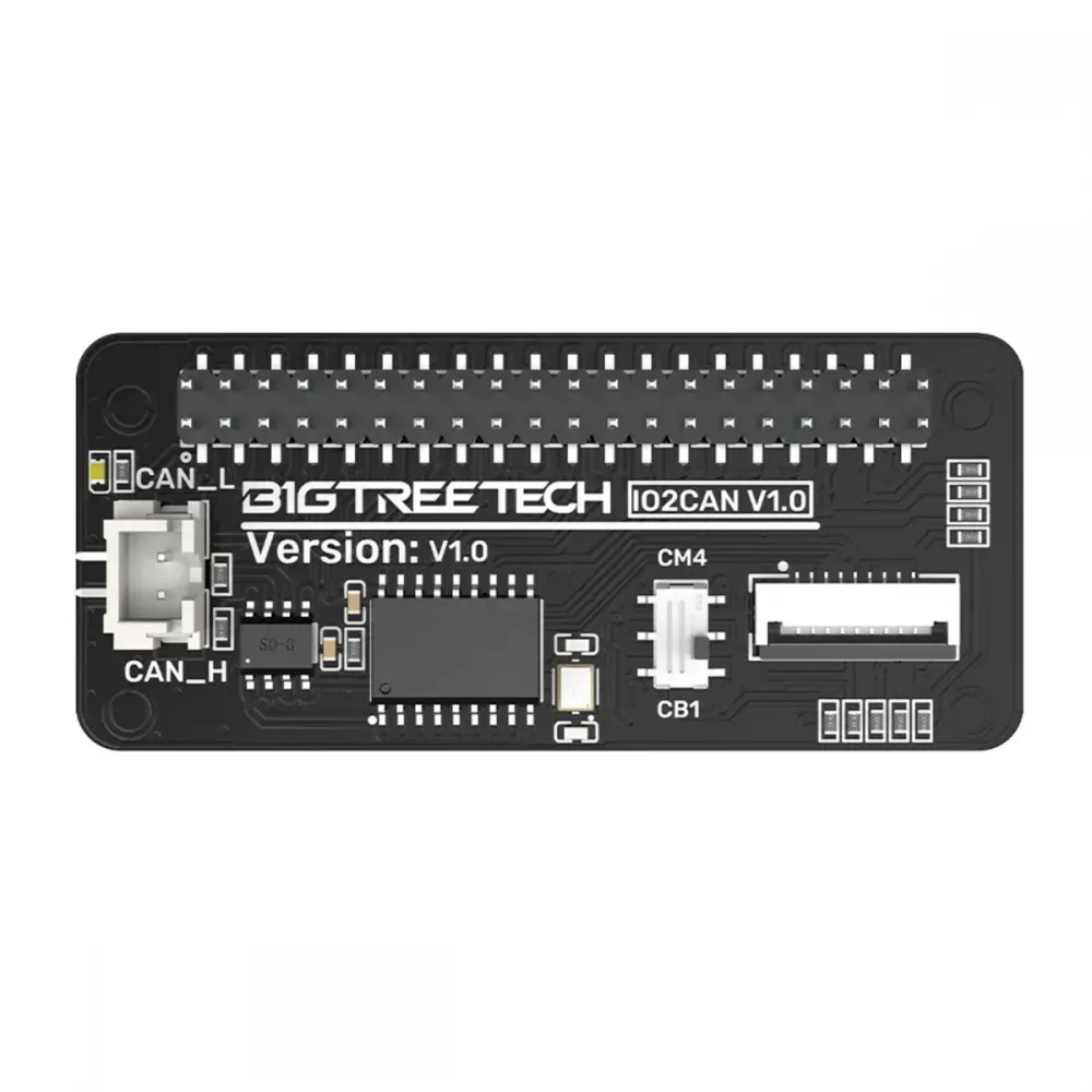
BIGTREETECH IO2CAN V1.0 is an SPI-to-CAN bus adapter for Klipper that plugs into a compatible 40-pin GPIO header. It adds an MCP2515-based CAN interface to a BIGTREETECH CB1, Raspberry Pi, or CM4 fitted to a suitable carrier board without occupying a USB port.
The board integrates the CAN controller, transceiver and level translation needed for either CB1 or the Raspberry Pi/CM4 pin arrangement. It also provides an FPC output for the BIGTREETECH TFT35 SPI V2.1 display.
CAN_H and CAN_L. It does not power the toolboard. IO2CAN also has a fixed 120 Ω terminator, so it must be installed at one of the two physical ends of the bus.
Main features
- SPI-to-CAN conversion through an MCP2515 controller.
- SN65HVD230 CAN transceiver.
- 12 MHz oscillator matching BIGTREETECH's official setup.
- Hardware selector for CB1 or Raspberry Pi/CM4.
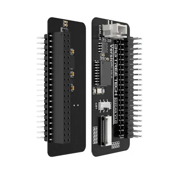
- Male and female 40-pin GPIO headers for stacked mounting.
- Two-way connector marked
CAN_HandCAN_L. - Integrated fixed 120 Ω termination resistor.
- 9-contact FPC output for a TFT35 SPI V2.1 display.
- Internal 1.8 V to 3.3 V signal translation for CB1.
Technical specifications
| Feature | Value |
|---|---|
| Model and revision | BIGTREETECH IO2CAN V1.0 |
| Host interface | SPI through a compatible 40-pin GPIO header |
| CAN controller | MCP2515 |
| CAN transceiver | SN65HVD230 |
| Oscillator | 12 MHz |
| CAN output | CAN_H and CAN_L; no power output |
| Termination | Fixed 120 Ω between CAN_H and CAN_L |
| Display interface | 9-contact FPC, SPI for display and I2C for touch |
| Power | From the 5 V and 3.3 V rails on the GPIO header |
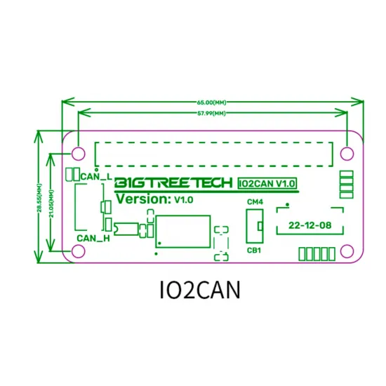
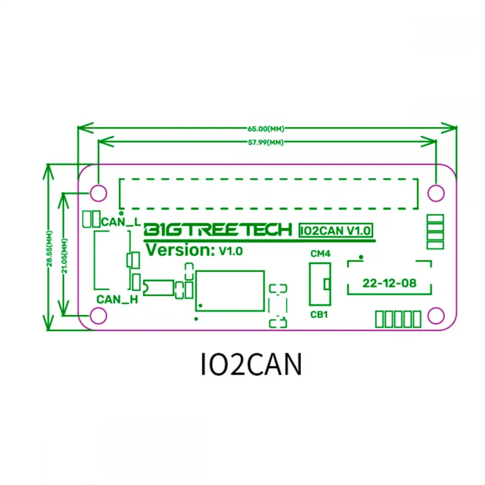
| PCB size | 65.00 × 28.55 mm |
| Mounting centres | 57.99 × 21.05 mm |
| Contents | 1 IO2CAN V1.0 module |
Compatibility checks
| Device | Compatibility | Conditions |
|---|---|---|
| BIGTREETECH CB1 | Manufacturer-documented | Carrier with a 40-pin GPIO header, selector on CB1, compatible OS image and MCP2515 overlay enabled. |
| Raspberry Pi | Manufacturer-documented | Compatible GPIO header, selector on CM4 and MCP2515 overlay configured. |
| Raspberry Pi CM4 | Carrier-dependent | The CM4 must be fitted to a carrier that correctly exposes the 40-pin GPIO; selector on CM4. |
| Manta M8P V2 | Conditional | Depends on the fitted CB1/CM4, header orientation, available clearance and operating-system configuration. |
| TFT35 SPI | Intended hardware interface | Display revision, FPC cable, operating system and overlays must match the installation. |
| EBB36 GEN2 and EBB42 GEN2 | CAN bus compatible | Matching bitrate, correct firmware, separate power, correct H/L wiring and exactly two terminators. |
A shared 40-pin form factor is not sufficient proof of compatibility: pinout, logic levels, operating system and MCP2515 support must all match. A CM4 installation also requires a suitable carrier board.
If the host has no compatible GPIO header or a USB connection is preferred, the BIGTREETECH U2C USB-to-CAN adapter is an alternative, while CAN firmware, bitrate and termination still need to be checked.
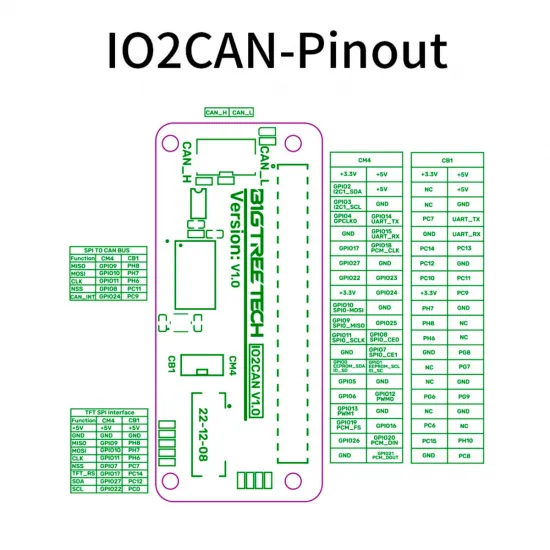
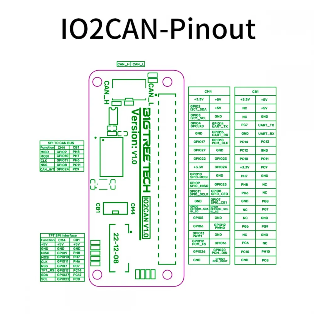
CAN adapter pin usage
| Function | Raspberry Pi / CM4 | CB1 |
|---|---|---|
| MISO | GPIO9 | PH8 |
| MOSI | GPIO10 | PH7 |
| SPI clock | GPIO11 | PH6 |
| MCP2515 chip select | GPIO8 | PC11 |
| CAN interrupt | GPIO24 | PC9 |
Mounting and CAN wiring
- Fully power down the host, controller board and every toolboard.
- Select
CB1for a BIGTREETECH CB1 orCM4for Raspberry Pi/CM4. Never move the selector while powered. - Carefully align both GPIO rows. An offset connection may route power to the wrong pins.
- Connect
CAN_HtoCAN_HandCAN_LtoCAN_Lwith a twisted pair. - Power each toolboard through its specified input. The two IO2CAN contacts do not supply voltage.
- Place IO2CAN at one physical end of the bus. Enable a second 120 Ω terminator at the opposite end and disable any intermediate termination.
- With all power removed, measure between CAN_H and CAN_L: two 120 Ω terminators in parallel should read approximately 60 Ω.
Secure the CAN cable, keep it away from power wiring where practical, and allow for continuous machine movement. A loose H/L contact or poor crimp can cause intermittent disconnects.
Raspberry Pi or CM4 setup
BIGTREETECH instructs users to enable SPI and load the MCP2515 overlay with the board's 12 MHz oscillator and GPIO24 interrupt:
dtparam=spi=on
dtoverlay=mcp2515-can0,oscillator=12000000,interrupt=24,spimaxfrequency=10000000
Add these lines to the boot configuration and reboot. BIGTREETECH's original path is /boot/config.txt; recent distributions may use /boot/firmware/config.txt, so verify the path used by the installed image.
BIGTREETECH CB1 setup
On a recent CB1 system image, edit /boot/BoardEnv.txt and enable the MCP2515 overlay:
overlays=mcp2515CB1 image v2.2.1 also required the sun50i-h616-biqu.dtb file to be replaced by the corrected revision in the IO2CAN repository. BIGTREETECH states that this replacement is unnecessary on versions later than v2.2.1; use a current official image for a new installation.
Creating the Klipper CAN interface
The host and every node must use the same bitrate. BIGTREETECH's IO2CAN-specific example uses 500 kbit/s; combined with Klipper's current transmit-queue recommendation, /etc/network/interfaces.d/can0 can contain:
allow-hotplug can0
iface can0 can static
    bitrate 500000
up ip link set $IFACE txqueuelen 128can0 alone does not reconfigure node firmware.
Reboot and verify controller initialisation:
dmesg | grep -i '\(can\|spi\)'
ip link show can0
The log should include a message equivalent to MCP2515 successfully initialized, and the interface should display the configured queue length.
Finding and registering a Klipper toolboard
With a new node powered, wired and not yet registered, query its UUID:
~/klippy-env/bin/python ~/klipper/scripts/canbus_query.py can0Add the returned identifier to printer.cfg under a descriptive MCU name:
[mcu toolhead]
canbus_uuid: 11aa22bb33cc
canbus_query.py is intended to discover previously unseen nodes. Do not use it as a ping tool or run it during a print. Once all UUIDs have been registered, retain them in the configuration.
Using a TFT35 SPI display
The FPC connector carries 5 V, ground, SPI for display data and I2C for the touch controller on the BIGTREETECH TFT35 SPI display. Operation depends on the display revision, cable, host and overlays available in the operating-system image.
CAN and display functions share the SPI bus with separate chip-select lines. Where CAN communication is critical, verify support in the selected image and complete an extended stability test before relying on a multi-device SPI setup.
Marlin and RepRapFirmware
IO2CAN is not configured directly in Marlin or RepRapFirmware. It is a Linux host adapter whose official procedure targets Klipper. It does not by itself turn a Marlin or RepRapFirmware controller into a CAN node, nor does it replace the firmware and configuration required by each toolboard.
Dimensions
The PCB measures 65.00 × 28.55 mm, with the four mounting centres forming a 57.99 × 21.05 mm rectangle. Also check the available height for both GPIO headers, the CAN connector and the FPC cable inside the electronics enclosure.
See the official BIGTREETECH IO2CAN documentation for the schematic, pinout, dimensions, legacy DTB file and configuration instructions.