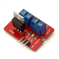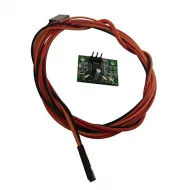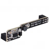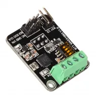


- Stock: 31
- Model: 3MOS-MKS

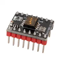
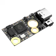
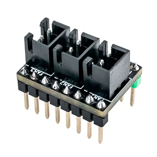
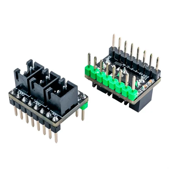
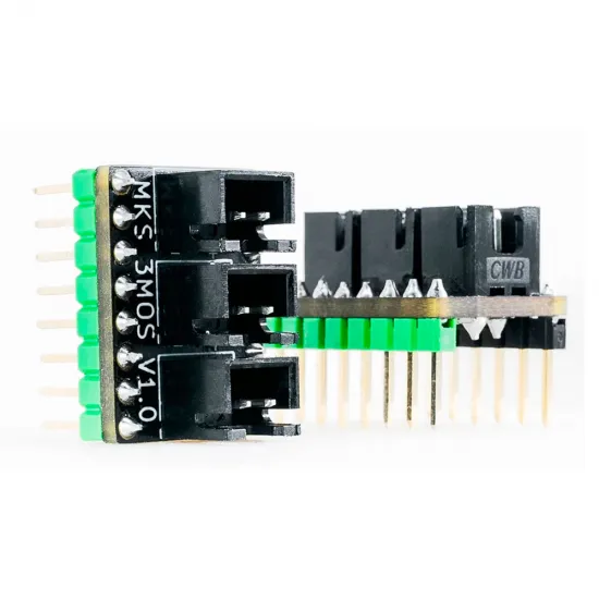
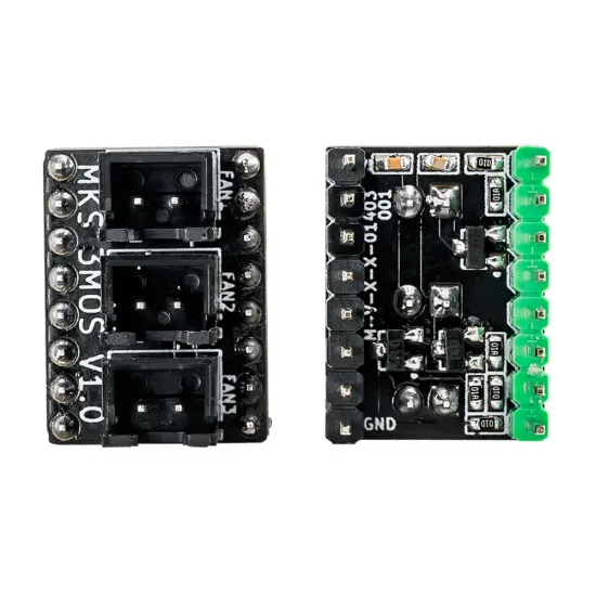
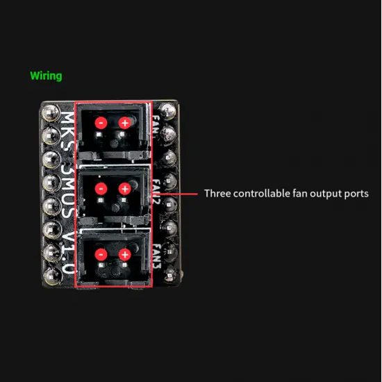
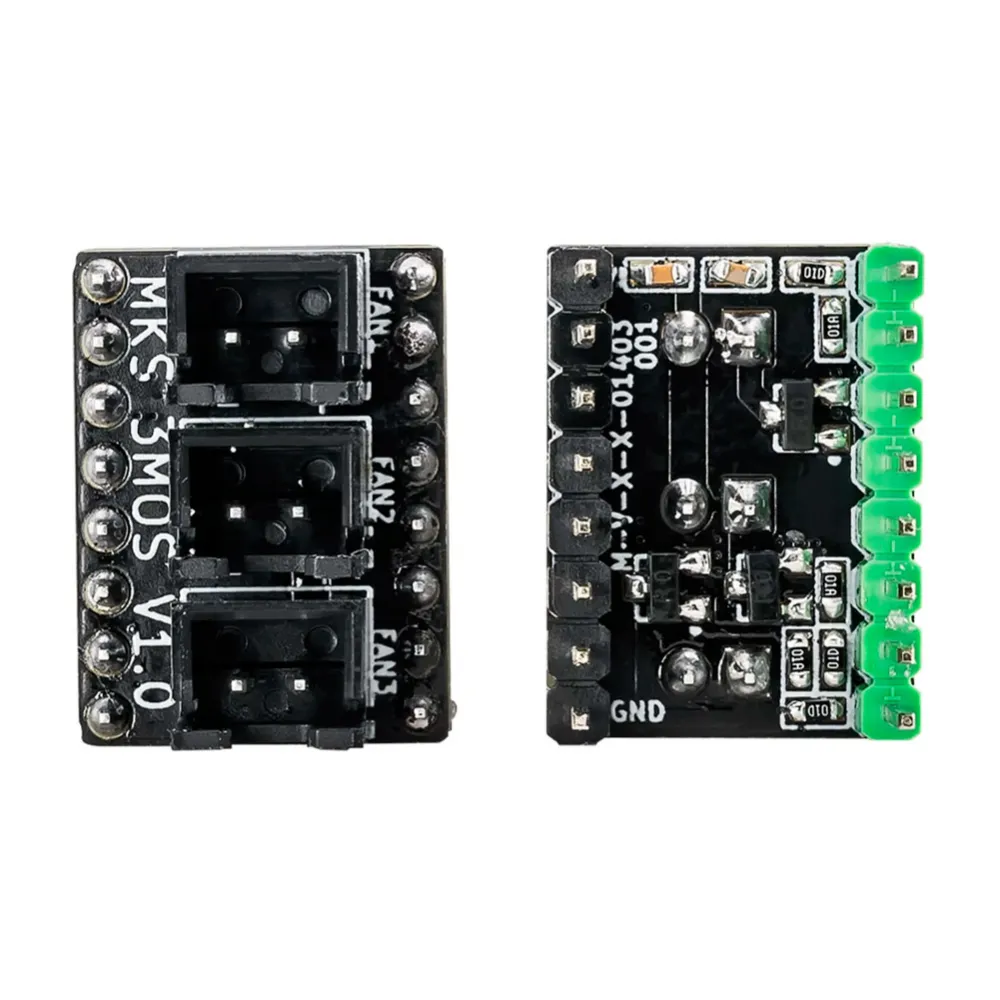
The MKS 3MOS V1.0 converts a spare stepper-driver socket into three independently controlled fan outputs. It repurposes the socket's ENABLE, STEP and DIR signals to control FAN1, FAN2 and FAN3 respectively, making it particularly useful on boards with more axes than the printer requires.
This is not a splitter for a single output: every connector has its own MOSFET and can be controlled separately in firmware. The occupied socket can no longer drive a motor, and installation requires the board pinout, orientation and bus voltage to be checked first.
Main features
| Feature | Specification |
|---|---|
| Revision | MKS 3MOS V1.0 |
| Function | 3 independent MOSFET fan outputs |
| Installation | Spare STEP/DIR driver socket with compatible format and pinout |
| Output supply | 12-24 V DC, drawn from the socket's VMOT pin |
| Current | Less than 1 A on each output; combined load must also be suitable for the controller board |
| Signals | FAN1 = ENABLE, FAN2 = STEP, FAN3 = DIR |
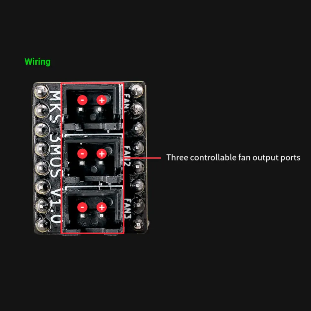
| Load connectors | 3 keyed 2-pin connectors |
| PCB dimensions | 20.32 × 15.24 mm |
| Contents | 1 MKS 3MOS module; controller, fans and wiring not included |
How it works
The positive pin of all three connectors is supplied directly by VMOT, while the module switches each fan's negative return independently. The output voltage is therefore not selectable on the 3MOS: it is the controller's motor-bus voltage. If VMOT is 24 V, all three fans must accept 24 V; a 12 V fan requires a suitable voltage converter.
The current rating must be applied conservatively: no output should reach 1 A, and the combined current must also remain within what the controller's socket, PCB tracks and VMOT supply can safely carry. This module is intended for low-voltage, low-current fans; it must not be used as a controller for a heated bed, heater cartridge, motor, solenoid or other power load.
Controller-board compatibility
A controller is compatible when it has an unused plug-in driver socket with matching VMOT, GND, ENABLE, STEP and DIR positions. Motor-bus voltage, logic levels and firmware pin assignment must also be suitable. Physical similarity to an A4988 or plug-in TMC driver is not enough to guarantee compatibility.
The MKS 3MOS family is documented for suitable-socket MKS Robin boards, MKS Gen-L/Gen-I, MKS SGen-L, MKS Monster8 and MKS TinyBee, but several revisions exist: always check the schematic of the exact board and select an axis that is not required for a motor. It is not a direct expansion for controllers with all drivers integrated or without a compatible STEP/DIR socket.
Marlin configuration
The physical relationship is fixed: FAN1 uses ENABLE, FAN2 uses STEP and FAN3 uses DIR from the selected socket. For an E1 installation, MKS provides this pattern:
#define FAN1_PIN E1_ENABLE_PIN
#define FAN2_PIN E1_STEP_PIN
#define FAN3_PIN E1_DIR_PIN
This is an example, not a universal configuration. Check your board's pins file and the fan numbering already used by your Marlin version: some configurations must begin with FAN2, FAN3 or a higher index to avoid replacing an existing output.
Once assigned, fans are controlled with M106 Pn S0 through M106 Pn S255, where n is the actual fan index. To stop a specific output, identify it with M106 Pn S0; M107 normally acts on the default fan.
Klipper configuration
In Klipper, create one [fan_generic] section per output and use the MCU pin that corresponds to ENABLE, STEP or DIR on the selected socket:
[fan_generic auxiliary_fan_1]
pin: <ENABLE_MCU_pin>

[fan_generic auxiliary_fan_2]
pin: <STEP_MCU_pin>

[fan_generic auxiliary_fan_3]
pin: <DIR_MCU_pin>E1_ENABLE_PIN, E1_STEP_PIN and E1_DIR_PIN are Marlin-style names and must not be copied literally into Klipper. Obtain the actual pins from the controller schematic or its official configuration file. Test one channel at a time before connecting all fans.
Safe installation
- Fully power down the printer and disconnect USB as well.
- Locate VMOT and GND on both the socket and module. Do not infer orientation from connector position.
- Confirm that the socket is not required for a motor and that its signals can be reassigned.
- Verify that VMOT voltage matches every connected fan.
- Insert the module without shifting either row and wire every load according to the + and - markings.
- Configure and test each channel separately while checking fan start-up and module temperature.
The 2-wire fan cable with XH2.54 connector can be used to prepare or extend the wiring, provided its polarity and wire order are checked against the module silkscreen before connection.
It is for you if...
- Your controller has a spare driver socket and you need three independently controlled fans.
- You can verify the exact board revision's pinout and configure Marlin or Klipper.
- Your fans use the same voltage as VMOT and draw comfortably less than 1 A per output.
It is not for you if...
- Every driver socket is occupied or all drivers are integrated on the board.
- You need a fan voltage different from the motor bus without adding a converter.
- You intend to control heaters, motors, solenoids or loads close to or above 1 A.
- You cannot verify orientation, pinout and firmware assignment before power-up.