

- Stock: 2
- Model: MELLOW-C8P-M2WE

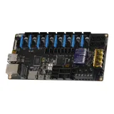
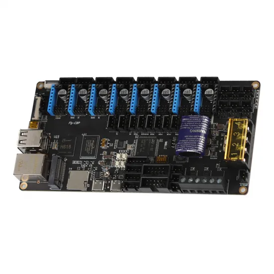
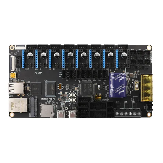
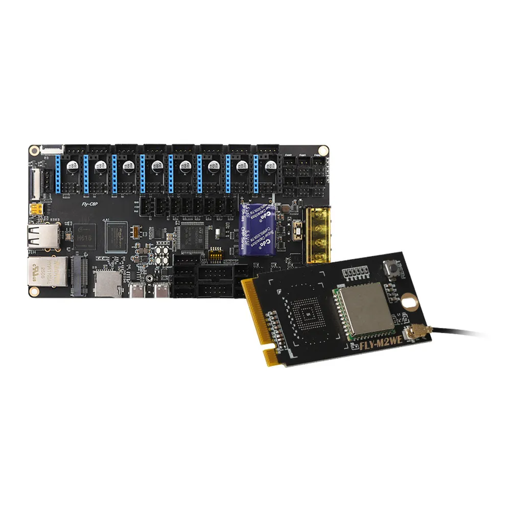
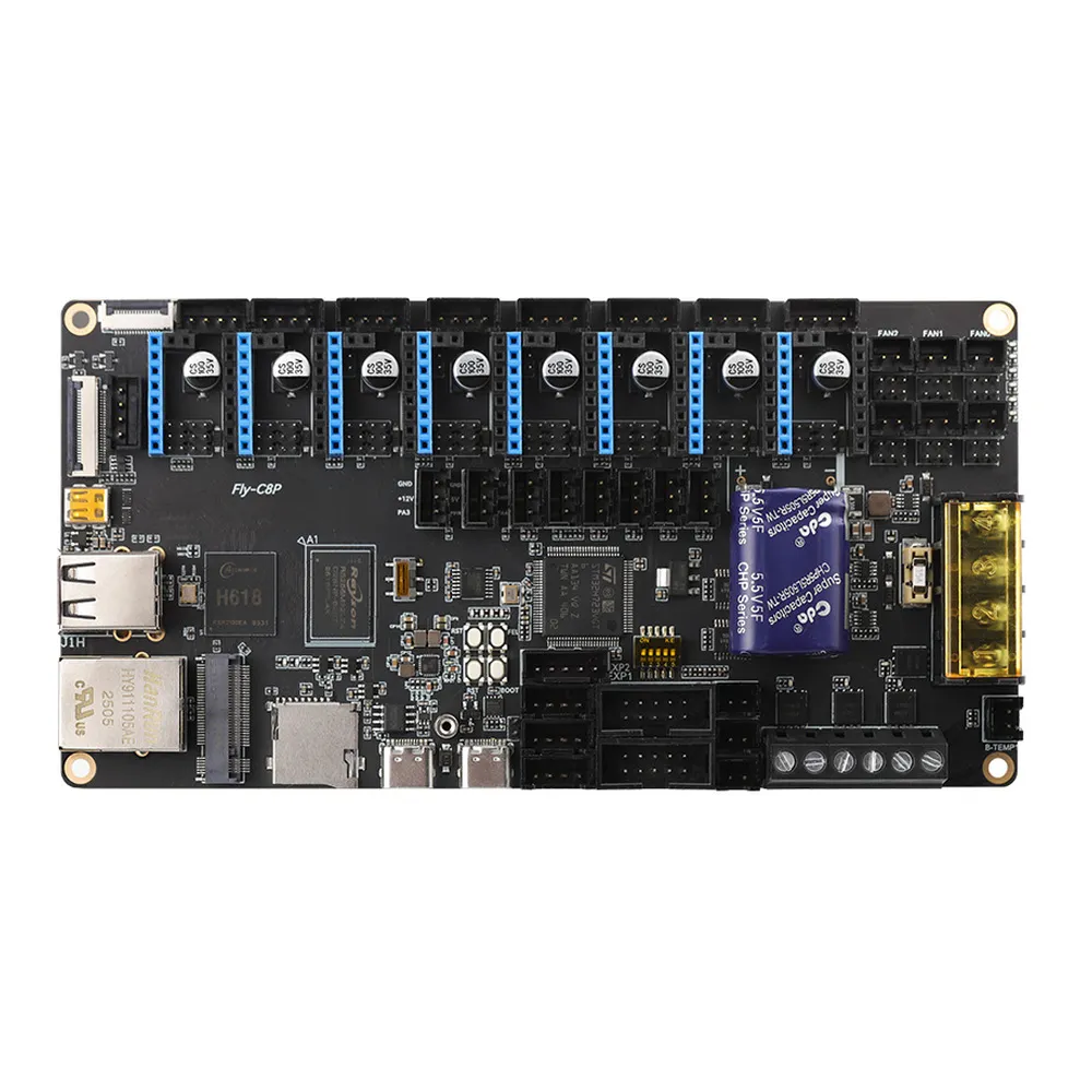
The Mellow FLY C8Pro with M2WE combines the computer running Klipper and the motion-control electronics on one board. It features a quad-core Allwinner H618 with 1 GB RAM, an STM32H723 ARM Cortex-M7, eight independent driver sockets and connections for heaters, fans, probes and CAN toolboards.
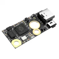
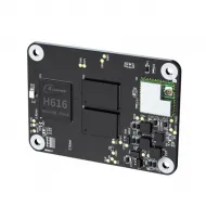
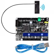
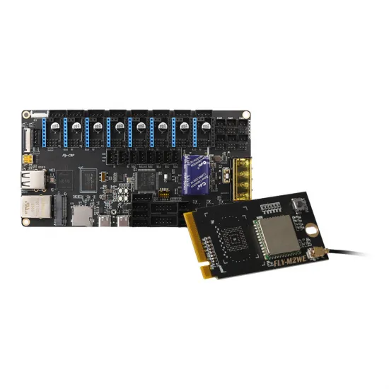
This set includes the M2WE module with eMMC storage and Wi-Fi, already installed, together with an antenna and connection accessories. You do not need to add a Raspberry Pi to provide the Klipper host computer. Motor drivers are purchased separately, so you can select their number and specifications to suit your printer.
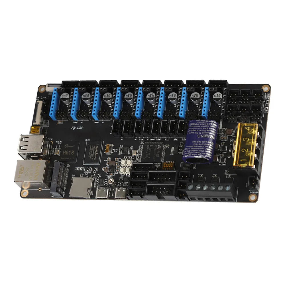
Integrated hardware with separate roles
In a conventional Klipper installation, a Linux computer prepares motion while a microcontroller executes timed motor and output commands. The C8Pro incorporates both: the H618 handles the operating system, web interface and Klipper services, while the STM32H723 handles real-time control. This provides a full web interface without a separate dedicated host computer.
The M2WE adds eMMC storage and Wi-Fi connectivity; it is not the main processor or a second motion controller. Its M.2 interface uses a FLY-specific protocol and is not a socket for a generic NVMe SSD or M.2 module.
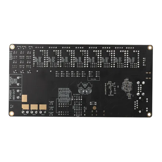
Mellow documents this hardware within its FLY ecosystem, providing pinouts, reference configurations, electrical schematics and mounting models. It is particularly useful for a configurable machine or an electronics upgrade needing more motors and connections.
What it adds to your printer
- Integrated Klipper host: fewer separate modules and fewer power connections between the host computer and motion board.
- Eight independent sockets: capacity for multiple Z motors, additional extruders or other layouts. An available socket does not mean your machine needs to use it.
- Replaceable drivers: choose UART, SPI or STEP/DIR modules compatible with the socket, voltage and firmware configuration.
- Ethernet and Wi-Fi: wired networking or wireless connectivity through the included M2WE. Ethernet is useful for initial setup and troubleshooting.
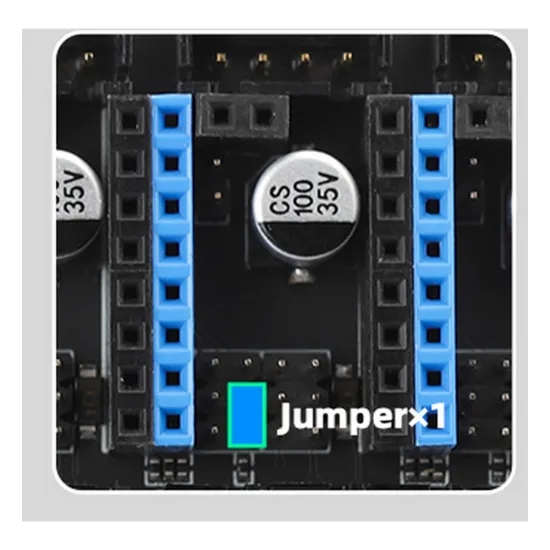
- Six fan outputs: part, hotend and electronics cooling, with available supply selection by jumpers for each channel.
- CAN toolboard connectivity: move extruder and sensor functions to a toolboard, using the appropriate firmware and wiring.
The manufacturer provides FlyOS/FAST images with Klipper, Moonraker, Mainsail, Fluidd, KlipperScreen and Crowsnest. This simplifies the software environment, but motor settings, temperatures, limits and homing must still be adapted to your machine. Processor speed alone does not determine printing speed.
Technical specifications
| Model | Mellow FLY C8Pro V1.0 with M2WE |
|---|---|
| Host computer | Allwinner H618, quad-core 64-bit Cortex-A53; 1 GB DDR4 |
| Motion microcontroller | STM32H723VGT6, 32-bit ARM Cortex-M7, up to 550 MHz |
| Power supply | 12–24 V DC; do not connect to 36 or 48 V |
| Motor drivers | 8 sockets; UART, SPI and STEP/DIR modes; drivers not included |
| Included storage and Wi-Fi | M2WE with eMMC; 2.4 and 5 GHz Wi-Fi and antenna |
| Host connections | 2 USB 2.0 ports, 100 Mb/s Ethernet, micro-HDMI, FPC-HDMI, TFT and serial connections |
| Heaters | 1 bed output and 3 hotend outputs |
| Temperature | 4 NTC 100 kΩ inputs; physical 4.7 kΩ pull-up resistors |
| Fans | 6 two-wire PWM outputs; VIN, 12 V or 5 V selection by jumpers |
| Expansion | CAN, BLTouch/probe, EXP1/EXP2 and 2 RGB connections |
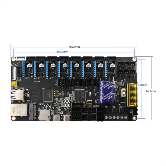
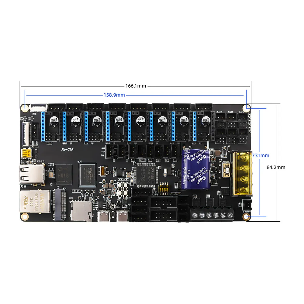
| Nominal PCB dimensions | 166.1 × 84.2 mm; nominal mounting-hole spacing 158.9 × 77.1 mm |
Allow additional space for connectors, cables, driver modules and cooling. PCB dimensions are not the dimensions of the fully wired assembly.
Motors, drivers and project compatibility
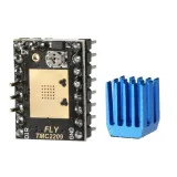
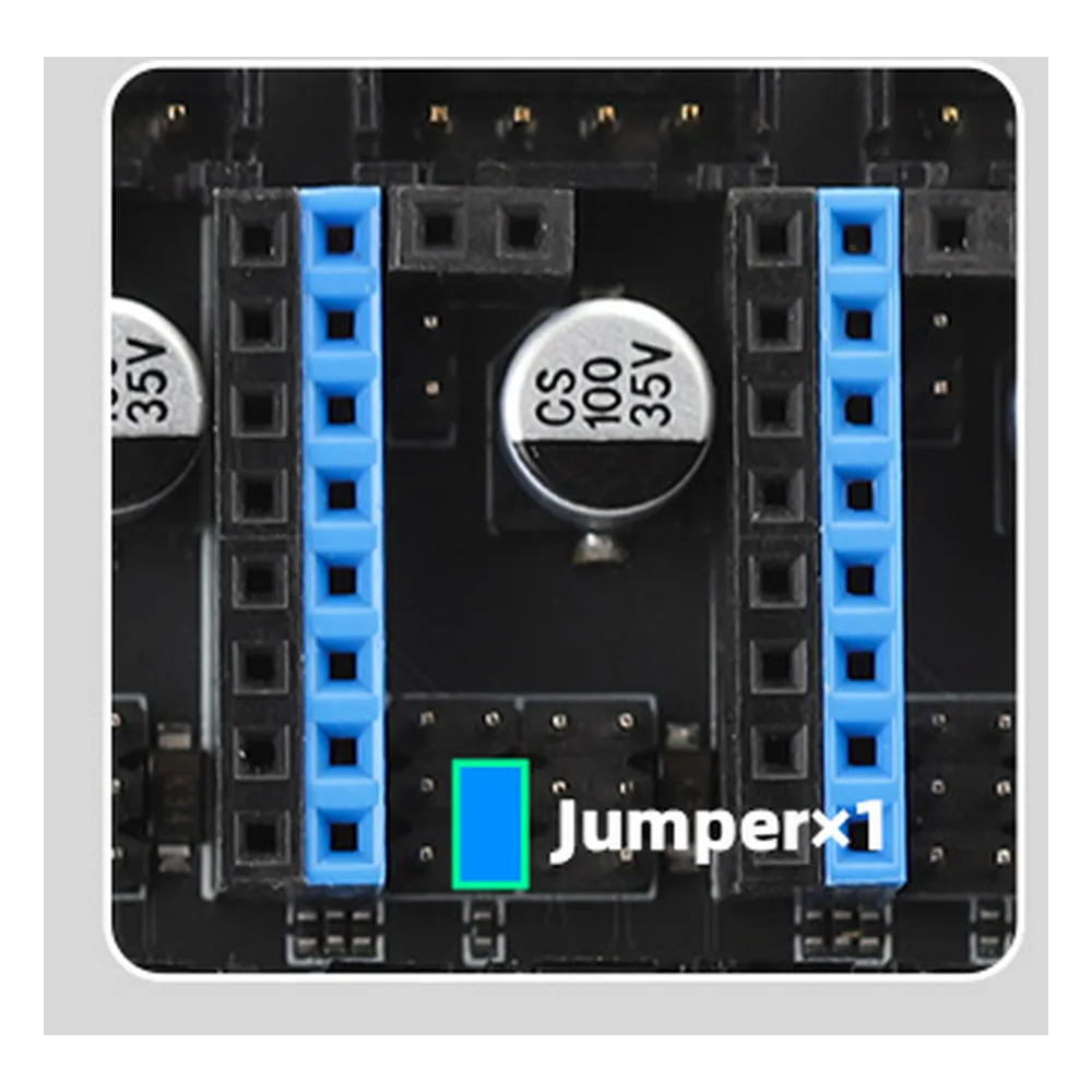
The Mellow FLY TMC2209 drivers with heatsinks are an option for two-phase bipolar motors in 12 or 24 V installations. UART communication allows current and parameters to be set through Klipper. Check orientation, UART selection and jumpers before installation; fit the heatsinks and provide suitable ventilation.
The C8Pro can provide electronics for Cartesian, CoreXY or independent multi-Z projects. For example, six drivers can cover X, Y, three Z motors and an extruder in a Voron Trident-style layout. A Voron 2.4-style layout with four Z motors uses six mainboard drivers for X, Y and Z, and can place the extruder driver on a toolboard.
These examples describe motor allocation, not a direct replacement for the original electronics. Check mounts, connections, load power, probing and machine-specific configuration. Not every socket has a documented DIAG input: consult the pin map before planning sensorless homing.
Power, fans and heater loads
Disconnect the power supply before fitting drivers, changing jumpers or connecting motors. Observe polarity, use suitable terminals and mount the board on insulating supports in a ventilated enclosure. Do not place the PCB on a metal surface or connect/disconnect a motor while powered.
On fan outputs, VIN is the input voltage: with a 12 V power supply, this position does not provide 24 V. Jumpers do not automatically detect a fan's voltage. Select a compatible supply for each fan before connecting it and do not change selection while powered.
| Output | Stated maximum with 24 V input | Stated maximum with 12 V input |
|---|---|---|
| Bed | 15 A | 7.5 A |
| Hotend heater | 6 A per output | 3 A per output |
| Fan | 1 A per output | 0.5 A per output |
These are manufacturer-stated port limits, not a guarantee that all outputs can operate continuously at their maxima at the same time. Size the power supply, fuses, wire gauge, connectors and cooling with headroom. Board input voltage and the voltage selected for a fan are different parameters.
Temperature inputs require the curve of the actual installed sensor. An NTC 100 kΩ sensor is not automatically a Beta 3950 sensor. PT100, PT1000 and thermocouple sensors require appropriate configuration and interfaces; do not reuse a thermistor configuration without checking.
Getting started with Klipper
- Check assembly with power disconnected: polarity, drivers, UART/SPI jumpers, fan voltage and clearance between the PCB and chassis.
- Connect the host to your network: Ethernet simplifies first access. For Wi-Fi, fit the antenna and configure a compatible network through FlyOS. If a combined-band SSID causes problems, temporarily try a separate network or Ethernet.
- Check the M2WE system: the image must be for the C8Pro's H618, not the older FLY C8. If the installed system works, reflashing is not required to get started. Back up your configuration before reinstalling; writing an image erases the selected device.
- Configure the internal MCU connection: for normal use, set the communication DIP to the upper position specified by the manufacturer, connecting the STM32 to the integrated host. The lower position connects it to the external USB-C port; this is different from the host's USB ports.
- Read the actual device identifier: use Mainsail/Fluidd device information or the official procedure. Another board's USB path or CAN UUID is not valid for your unit.
- Adapt printer.cfg: assign pins, kinematics, transmission, current, sensors, temperature limits and homing. A template is a reference map, not a universally safe configuration.
- Test in stages: communication and temperature readings first, then fans, motor direction and homing. Validate sensors and thermal protection before controlled heating tests.
For USB motion firmware, this C8Pro's documentation specifies STM32H723, a 128 KiB bootloader, a 25 MHz crystal and USB PA11/PA12. For USB–CAN bridge operation, select that mode and CAN pins PB8/PB9. These are alternative connection setups: do not mix one setup's USB identifier with another's CAN UUID.
The board's NTC inputs use 4700 Ω pull-ups, matching Klipper's usual default. Set sensor_type to the correct sensor curve; do not copy another board's pull-up value. Temperature limits must match the complete hotend, sensor and materials.
Klipper driver pin map
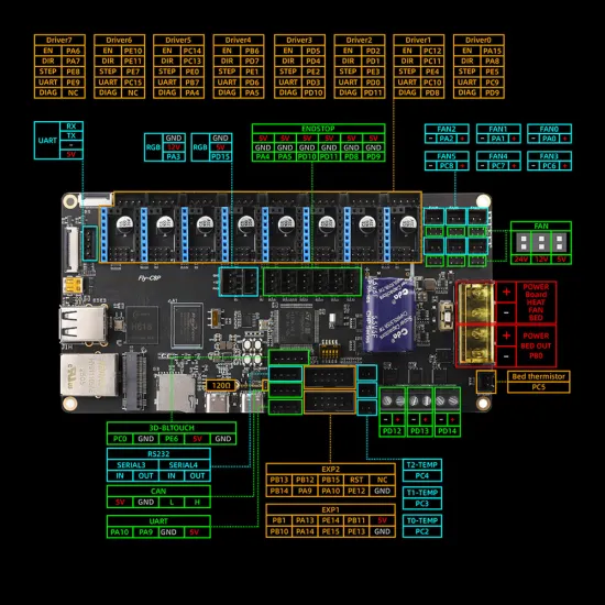
This table identifies microcontroller signals. UART/CS is UART for a UART driver or chip-select for an SPI driver, depending on hardware setup. Socket enable signals are configured active-low in Klipper, using ! before the EN pin.
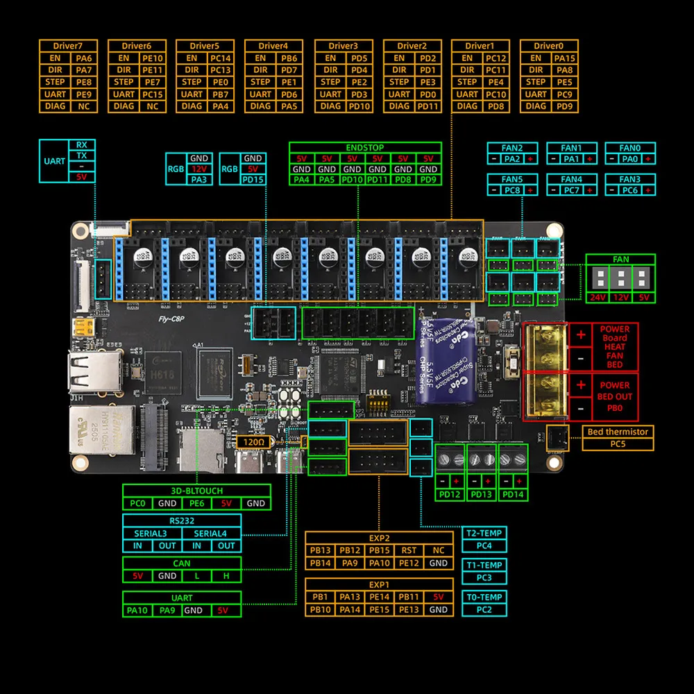
| Socket | STEP | DIR | EN | UART/CS | DIAG |
|---|---|---|---|---|---|
| DRIVER0 | PE5 | PA8 | !PA15 | PC9 | PD9 |
| DRIVER1 | PE4 | PC11 | !PC12 | PC10 | PD8 |
| DRIVER2 | PE3 | PD1 | !PD2 | PD0 | PD11 |
| DRIVER3 | PE2 | PD4 | !PD5 | PD3 | PD10 |
| DRIVER4 | PE1 | PD7 | !PB6 | PD6 | PA5 |
| DRIVER5 | PE0 | PC13 | !PC14 | PB7 | PA4 |
| DRIVER6 | PE7 | PE11 | !PE10 | PC15 | Not documented |
| DRIVER7 | PE8 | PA7 | !PA6 | PE9 | Not documented |
For example, a TMC2209 in DRIVER0 uses uart_pin: PC9. FLY TMC2209 drivers in this family use sense_resistor: 0.110. run_current is expressed in RMS amperes and must match the motor and cooling. Check communication using DUMP_TMC STEPPER=stepper_x if DRIVER0 is actually assigned to that axis; motor movement alone does not prove UART is working.
Sensorless homing requires DIAG and machine-specific calibration. Do not connect a mechanical endstop to an input shared with active DIAG without checking the circuit and jumpers. StallGuard is not a bed probe or an encoder correcting missed steps.
Reference pins for heaters, sensors and fans
| Function | Pin or assignment |
|---|---|
| E0 / T0 | Heater PD12 / temperature PC2 |
| E1 / T1 | Heater PD13 / temperature PC3 |
| E2 / T2 | Heater PD14 / temperature PC4 |
| Bed / bed sensor | Heater PB0 / temperature PC5 |
| FAN0–FAN5 | PA0, PA1, PA2, PC6, PC7 and PC8, respectively |
| Probe / BLTouch servo control | PC0 / PE6 |
| RGB | PA3 and PD15 |
A pin assignment does not establish electrical compatibility with a sensor. Check output voltage, polarity and signal type before connecting an electronic probe or endstop; do not feed 12 or 24 V directly into a logic input that cannot accept it.
Adding a CAN toolboard
The Mellow FLY SHT36 V3 Plus brings the extruder driver, heater, fans and sensors onto the toolhead and includes a LIS2DW accelerometer and MAX31865 circuit. It can be combined with the C8Pro in a Klipper CAN installation, adapting mounting, connections and configuration to the machine.
With suitable firmware, the C8Pro can act as a USB–CAN bridge, so this architecture does not necessarily need another USB–CAN adapter. All nodes must use the same bus speed; the documentation proposes 1,000,000 bit/s. Check termination at the two physical ends and avoid adding terminators at every intermediate device.
Power connection matters: the C8Pro CAN connector includes a 5 V pin. This cannot power the SHT36, which requires 12–24 V. Supply power through the appropriate input and connect CAN-H, CAN-L and the ground reference according to both devices' schematics. A CAN connector does not guarantee matching pin assignments on another board.
Included in the set
- One Mellow FLY C8Pro board.
- M2WE module with eMMC storage, installed.
- Wi-Fi antenna.
- USB cable.
- XH crimp connectors and jumpers.
- USB adapter for eMMC storage.
Plug-in drivers, power supply, motors, display and toolboard are not included. The eMMC adapter is for storage maintenance; it does not need to remain connected during normal operation.
It is for you if…
- You want Klipper electronics with an integrated host, without adding a Raspberry Pi.
- You need several independent motors and prefer selecting or replacing modular drivers.
- You are configuring a CoreXY, a multi-Z machine or a CAN toolboard installation.
It is not for you if…
- You need an identical replacement for an original board, with firmware and wiring ready for any printer.
- Your installation requires directly powering this board at 36 or 48 V.
- You need to fit a standard M.2 SSD to its FLY-specific socket.
Frequently asked questions
Do I need to buy a Raspberry Pi?
Not for the host computer: the H618 already performs that role. This set also includes M2WE/eMMC storage.
Are eight drivers included?
No. There are eight independent sockets; purchase only the modules required by your project's motor layout.
Can I use a 230 V bed?
Not directly from the board's bed output. A mains-powered bed requires an appropriate switching stage, protection and dedicated electrical installation by qualified personnel.
Is power-loss management a UPS?
No. FlyOS provides power-loss management functions using the hardware specified by Mellow, but it does not keep the printer running like a UPS. Safe shutdown and print recovery are different configurable functions; automatic recovery of every print is not guaranteed.
Can I use Marlin or RepRapFirmware?
This guide focuses on Klipper and FlyOS. Another firmware requires checking C8Pro H723-specific support and its connection to the integrated host; it is not an interchangeable firmware file.
Installation and reference documentation
Official FLY C8Pro documentation · Official pinout · M2WE module and storage · Klipper CAN guide