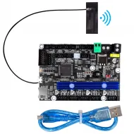


- Stock: 4
- Model: MELLOW-SHT36-V3P

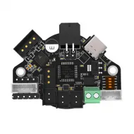
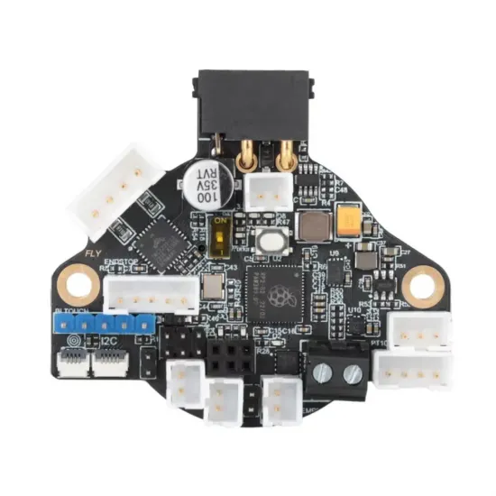
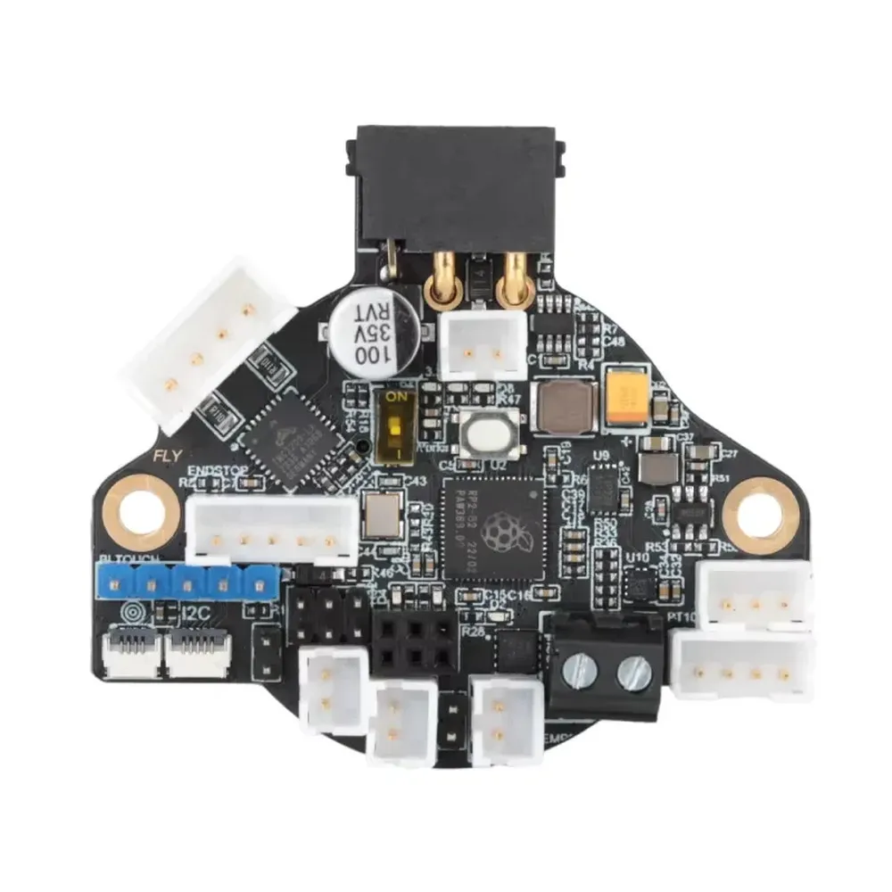
The Mellow FLY SHT36 V3 Plus brings extruder motor, heater, fan and sensor connections together on the printhead. Its CAN or RS232 link carries power and communication over four conductors, reducing the wiring harness travelling with the toolhead and helping create a tidier installation.
The defining feature of this Plus version is its onboard MAX31865 for PT100 and PT1000 sensors, alongside a TMC2209 driver and LIS2DW accelerometer. It suits a Klipper project needing a compact toolboard, resonance measurement and a dedicated RTD input without adding an external MAX31865 module.
What it brings to your build
- Fewer moving wires: toolhead peripherals connect locally, while the link to the main electronics combines power and data.
- Built-in TMC2209: controls one extruder motor through UART, without a separate StepStick driver for this function.
- PT100/PT1000 measurement: the MAX31865 accepts two-, three- or four-wire RTDs when switches and configuration match the sensor.
- LIS2DW accelerometer: measures resonances with Klipper to tune Input Shaper. Results depend on measurement and mechanics; this does not automatically correct every print artefact.
- Two controllable fan outputs: for part cooling and hotend cooling, with one shared voltage selector.
- Additional connections: endstop, levelling probe, addressable LEDs and CAN expansion for builds that need them.
Specifications of this version
| Feature | Mellow FLY SHT36 V3 Plus |
|---|---|
| Microcontroller | RP2040, dual-core ARM Cortex-M0+, 133 MHz. |
| Power supply | 12–24 V DC. 3.3 V logic. |
| Operating communication | CAN or RS232, selected physically and through matching firmware. |
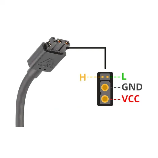
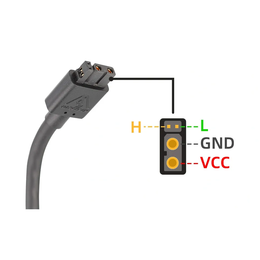
| Main connector | XT30 (2+2): two power contacts and two communication contacts. |
| Extruder driver | One onboard TMC2209 with UART control. |
| Temperature | TH0 for a 100 kΩ NTC or suitably configured PT1000; separate MAX31865 RTD input for PT100/PT1000. |
| Accelerometer | Onboard LIS2DW connected through SPI. |
| Fans | Two controllable DC outputs. Shared VCC / 12 V / 5 V selector; VCC is the board supply voltage. |
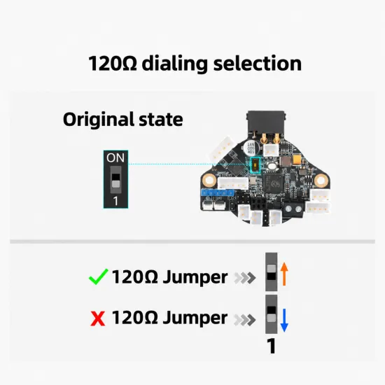
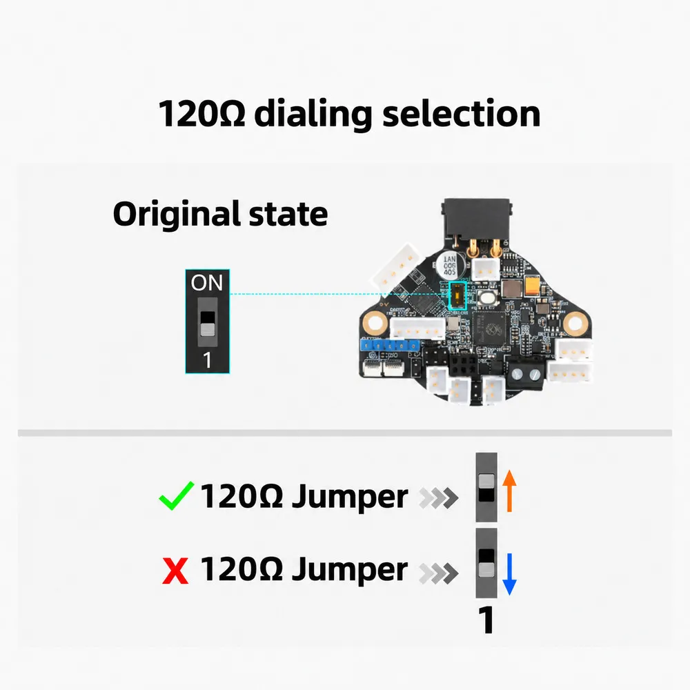
| CAN termination | 120 Ω resistor enabled by a switch. |
| USB-C | Available for programming. USB does not replace the peripheral power supply. |
| Firmware | Klipper. This Plus version does not include the LDC1612 or the RRF support advertised for the Max. |
Compatibility and choosing the board
Designed for Klipper printers and toolheads with a suitable mount for this board. It can be integrated into projects such as Voron 2.4 or Trident, but the actual extruder bracket, connector orientation and cable clearance must be checked: this does not mean direct fit on every Stealthburner or mechanical interchangeability with other toolboards.
The SHT36 format is intended for installations around 36 mm-class motors. Electrical compatibility also depends on motor current and coil ordering. A NEMA 17 motor, another extruder or a mount made for another board may require an adapter; four contacts alone do not establish matching wiring.
CAN needs a USB–CAN adapter or a mainboard configured as a USB–CAN bridge. The BIGTREETECH U2C is one option for this link, after checking its firmware, termination and bus speed. It does not replace the 12 or 24 V power supply.
Power supply, heater and fans
Choose peripherals rated for the voltage used. The heater receives the board supply voltage: do not connect a 12 V heater cartridge to a 24 V supply. Mellow publishes these operating limits for output sizing:
| Output | Board powered at 24 V | Board powered at 12 V |
|---|---|---|
| Heater | 5 A | 2.5 A |
| Fan port | 1 A | 0.5 A |
Allow headroom for continuous operation and account for the cable, connectors and combined consumption. As a calculation example, a 50 W cartridge at 24 V draws approximately 2.08 A; a 40 W cartridge at 12 V draws approximately 3.33 A, above the stated heater limit with a 12 V board supply.
Both fans share the voltage selector: you cannot independently select 5, 12 and 24 V for each output. VCC supplies the input voltage, and a 12 V input is not boosted to 24 V. Always disconnect power before moving the selector.
Conventional fan outputs switch the negative return. Do not confuse this terminal with a permanent ground for a four-wire fan's control signal; that installation needs a separate check of supply, ground and PWM signal.
CAN installation
- Disconnect power before wiring, moving switches or connecting the motor.
- Select CAN using the communication switches on the back. These are separate from the six-position MAX31865 selector and the 120 Ω termination switch.
- Connect VCC to the positive 12/24 V supply and GND to the negative; CAN-H to H and CAN-L to L. Check the XT30 (2+2) contacts and orientation, not just wire colours.
- Keep the data pair twisted, protect the cable route and provide toolhead strain relief. CAN expansion must respect bus topology, with short branches.
- Enable one 120 Ω termination at each physical bus end: two in total, not one per device. Enable this board's termination only when it is at an end.
- With the entire circuit unpowered, around 60 Ω between H and L is consistent with two parallel 120 Ω resistors. This checks termination, not the complete wiring.
- Use matching speeds in the adapter, board firmware and every bus node.
Compiling and starting Klipper
Mellow states that the board ships with Katapult for CAN at 1 Mbit/s. This bootloader allows Klipper installation but does not provide a ready-made printer configuration. If the bootloader has been changed, the application offset must match what is actually installed.
Keep your previous configuration and open the build menu in the host's Klipper installation:
cd ~/klipper
make menuconfig
For CAN with the Katapult described by Mellow, select extra low-level options; Raspberry Pi RP2040/RP235x architecture; rp2040 processor; 16KiB bootloader; CAN bus; RX GPIO1; TX GPIO0; speed 1000000 if your bus runs at 1 Mbit/s. Enable Optimize stepper code for 'step on both edges' and set !gpio5 under GPIO pins to set at micro-controller startup, as specified in this board's guide. Save and run make.
On a host with a conventional Klipper installation, query unassigned nodes with:
~/klippy-env/bin/python ~/klipper/scripts/canbus_query.py can0Do this when not printing. A device already assigned to an active Klipper instance may not appear. Use this board's UUID for flashing and for [mcu SHT36] with canbus_uuid:. Flash-tool paths vary between installations: check whether you use standalone Katapult or FlyOS tools, and avoid flashing the wrong node.
The Klipper CAN documentation and Mellow firmware guide cover host setup, flashing and recovery in more detail.
RS232 alternative
RS232 is another Klipper communication method, not USB printing or a CAN connection. It requires an interface compatible with Mellow's implementation, such as FLY UTOR or a mainboard with a documented matching port. Do not connect a TTL UART directly or assume compatibility with any serial adapter.
With power disconnected, select RS232 and use its matching firmware. The official guide specifies rp2040, No bootloader, UART0 on GPIO0/GPIO1, 250000 baud and startup !gpio5. Initial programming uses USB-C in BOOT mode with the UF2 file; this process replaces CAN Katapult. Then connect board IN to interface OUT, board OUT to interface IN and a common ground, while retaining the 12/24 V supply. Klipper uses serial: and the corresponding baudrate instead of canbus_uuid:.
Main toolhead configuration pins
Examples use MCU name SHT36. If you choose another name, change the prefix on every pin as well. Merge these settings into your existing configuration; do not duplicate extruder or fan sections when copying examples.
| Function | Pin / setting |
|---|---|
| Extruder motor | step_pin: SHT36:gpio7, dir_pin: SHT36:gpio6, enable_pin: !SHT36:gpio14. |
| TMC2209 UART | uart_pin: SHT36:gpio15, sense_resistor: 0.110. |
| HEAT0 heater | heater_pin: SHT36:gpio23. |
| TH0 temperature | sensor_pin: SHT36:gpio27. |
| FAN0 / FAN1 | SHT36:gpio13 / SHT36:gpio21. |
| Endstop | SHT36:gpio16; adjust pull-up and polarity for the device. |
| Probe / BLTouch control | SHT36:gpio22 / SHT36:gpio24; verify the probe pinout. |
| HV-IN input | SHT36:gpio20; check the dedicated jumper for a mechanical contact or proximity sensor. |
| Addressable LEDs | SHT36:gpio26; 5 V LED interface, not a 12/24 V analogue RGB strip. |
| LIS2DW / MAX31865 | CS SHT36:gpio12 / SHT36:gpio17. Shared SPI bus: spi0_gpio4_gpio3_gpio2. |
For HV-IN, the manufacturer's guide requires the jumper fitted for an ordinary mechanical contact and removed for the intended proximity sensor. Do not apply supply voltage to a logic GPIO or reuse this setting for a different probe without checking its connection.
TMC2209 run_current is RMS current and must suit the motor and cooling. The manufacturer's 0.8 A example is not mandatory for every extruder. Keep or calibrate your own gearing, rotation_distance, direction and Pressure Advance.
Choosing and configuring the temperature sensor
NTC thermistor or PT1000 on TH0
For a 100 kΩ NTC, use TH0 and that sensor's curve. Only a 100 kΩ beta 3950 sensor calls for sensor_type: Generic 3950, with sensor_pin: SHT36:gpio27 and a 4700 Ω pull-up; leave the PT1000 selection jumper open. Not every 100 kΩ sensor has the same curve.
A PT1000 connected directly to TH0 uses sensor_type: PT1000, the same GPIO27 and pullup_resistor: 1000, with the dedicated jumper closed. This is separate from the MAX31865 circuit: changing the sensor name alone does not change the physical input resistor.
PT100 or PT1000 through MAX31865
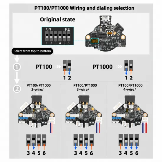
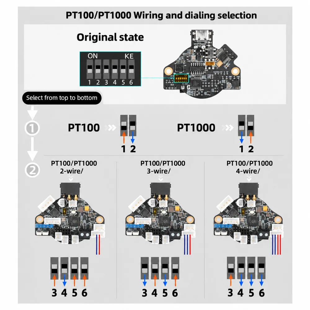
Connect the RTD to the dedicated four-contact MAX31865 port. Selection combines sensor type and wire count; set it without power and follow the numbers printed on the six switches.
| Selection | Switches ON | Switches OFF | Klipper setting |
|---|---|---|---|
| PT100 | 1 | 2 | rtd_nominal_r: 100; rtd_reference_r: 430. |
| PT1000 | 2 | 1 | rtd_nominal_r: 1000; rtd_reference_r: 4300. |
| Two wires | 3, 5, 6 | 4 | rtd_num_of_wires: 2. |
| Three wires | 4, 6 | 3, 5 | rtd_num_of_wires: 3. |
| Four wires | 3 | 4, 5, 6 | rtd_num_of_wires: 4. |
Combine one of the first two rows with the relevant wire-count row. For example, the two-wire Mellow PT1000 sensor with a 3 mm cartridge requires switches 2, 3, 5 and 6 ON; 1 and 4 OFF. Adapt its connection to the RTD port and check that its cartridge fits the heater block.
For this two-wire PT1000, the following lines replace the temperature settings in your [extruder] section:
sensor_type: MAX31865
sensor_pin: SHT36:gpio17
spi_bus: spi0_gpio4_gpio3_gpio2
rtd_nominal_r: 1000
rtd_reference_r: 4300
rtd_num_of_wires: 2
rtd_use_50Hz_filter: True
The 50 Hz filter suits installations with that mains frequency, such as Spain. Remove incompatible settings from the previous NTC input. For a different RTD, change sensor type, reference resistance and wire count in hardware and software. The MAX31865 does not turn an NTC thermistor into a PT100/PT1000.
Three- and four-wire connections can compensate lead resistance with a suitable sensor and installation; two-wire measurements still include it. Final accuracy also depends on the RTD, wiring and installation.
LIS2DW and Input Shaper
Configure the onboard accelerometer using the same hardware SPI bus as the MAX31865:
[lis2dw]
cs_pin: SHT36:gpio12
spi_bus: spi0_gpio4_gpio3_gpio2
Check its readings with ACCELEROMETER_QUERY CHIP=lis2dw. Then define [resonance_tester] with this accelerometer and a safe test point inside your printer's volume; follow the Klipper resonance measurement guide to check noise and run calibration.
On a CoreXY, the toolhead can measure X and Y motion. On a printer whose bed moves in Y, a sensor fixed to the toolhead does not correctly characterise bed resonances: measure that axis on the moving part. Do not copy axis orientation or a test point from another printer without checking.
Checks before printing
- Keep Klipper's thermal protections. Temperature limits must suit the complete hotend, sensor and wiring; installing a MAX31865 does not justify raising them.
- Before heating, verify a plausible ambient temperature and the response to a reading fault. For an abnormal reading, check sensor type, jumper, switches and connection.
- Check extruder direction at operating temperature under safe conditions; never connect or disconnect the motor while powered.
- Verify each fan responds to the correct control and the hotend fan starts as intended.
- Tune thermal control with
PID_CALIBRATE HEATER=extruder TARGET=...at a suitable temperature for your assembly. Validate changes before saving. - Secure the board and cables using spacers and strain relief, away from hot parts, rubbing and moving hazards. Avoid tight bends in the supplied cable.
Package contents
- One Mellow FLY SHT36 V3 Plus board.
- XT30 power and communication cable, approximately 1.5 m long.
- Loose connectors for preparing the installation wiring.
- One USB cable.
USB–CAN/RS232 adapter, Klipper host, motor, hotend, RTD sensor and toolhead-specific mount are not included.
It's for you if...
- You are building a Klipper toolhead and want tidier CAN or RS232 wiring.
- You need PT100/PT1000 through MAX31865 without adding another toolhead module.
- You want an onboard accelerometer and can adapt mounting and configuration.
It's not for you if...
- You need a direct replacement without checking mounting, wiring or firmware.
- Your project requires the Max variant's onboard LDC1612 or RRF support.
- Your loads exceed these output limits, or you need each fan's voltage independently selected using the board jumpers.