

- Stock: 10
- Model: PSU-36V10A360W
Model:

12V 5A 60W

12V 10A 120W

12V 15A 180W

12V 20A 250W Fan

12V 33A 400W

12V 40A - 500W

24V 10A 240W

24V 15A 360W

24V 20A 500W

24V 25A 600W

24V 33A 800W

36V 10A 360W

48V 10A 500W
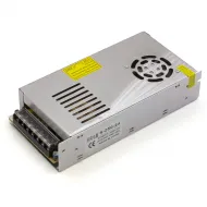
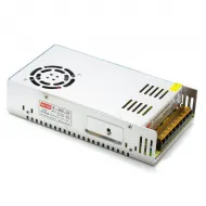
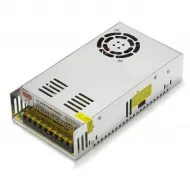
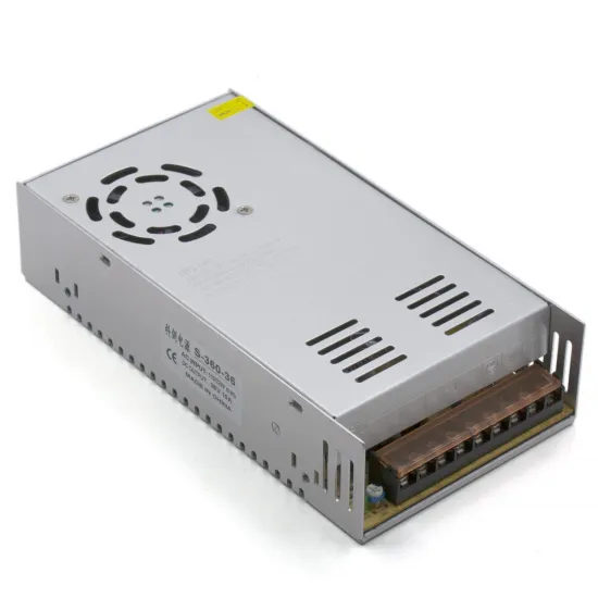
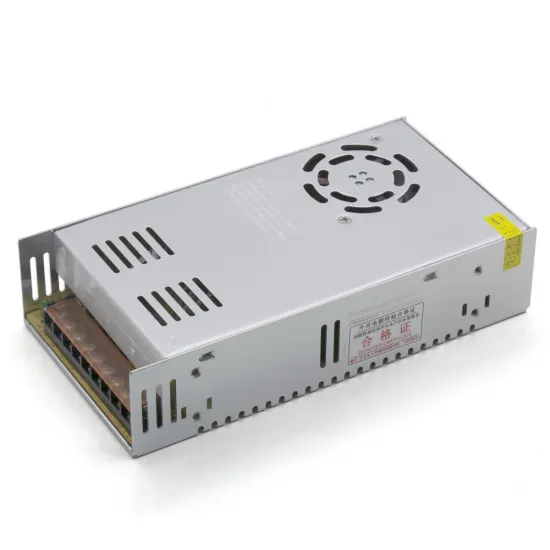
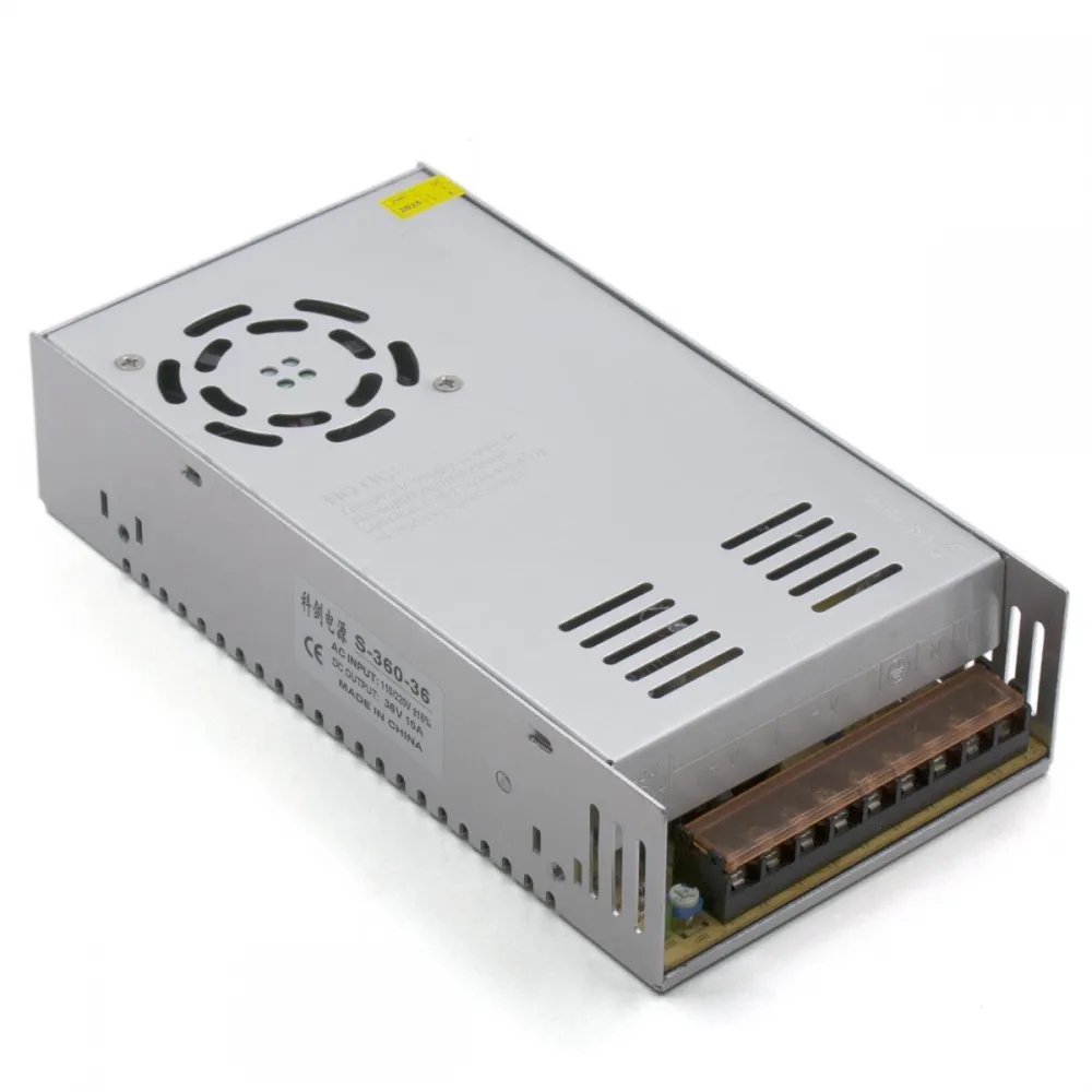
S-360-36 switching power supply rated at 36 V, 10 A and 360 W, with a ventilated metal enclosure and active cooling. It is intended for motors, CNC machines, automation and electronic projects that use a correctly sized 36 V DC rail.
It is also particularly useful as an auxiliary motor supply for a 3D printer. For example, it can power TMC2240 drivers through the MOTOR_POWER input of a BIGTREETECH Octopus Pro while the board and 24 V components retain their appropriate supply. This application must follow the conditions below because 36 V is also the TMC2240's maximum operating voltage.
Confirmed features
| Feature | Value |
|---|---|
| Type | AC/DC switching power supply for integration |
| Marked family | S-360-36 |
| Rated output | 36 V DC |
| Stated maximum current | 10 A |
| Rated power | 360 W |
| Input | Visible side selector; check the supplied unit's marking and position before connection |
| Cooling | Integrated fan and perforated enclosure |
| Environment | Indoor use, integrated in a protected and ventilated assembly |
Sizing the load
The stated 10 A and 360 W are nominal maximum ratings. Add the demand of every 36 V component that may operate simultaneously and account for acceleration, peaks, temperature, cooling and wiring voltage drop.
A conservative target for sustained load is approximately 80% of the stated capacity: around 8 A or 288 W. This is a project-design margin, not a revised nominal rating or a guarantee for every installation.
- Electrical power: P = V x I.
- Approximate current at 36 V: I = P / 36.
- If demand is close to 10 A, increase the available margin or split loads with appropriate protection.
- A driver's configured phase current must not be added as if it were a constant DC input current.
Terminals and distribution
The supply uses a terminal block for mains input and DC output. Always follow the markings on the supplied unit:
| Marking | Usual function |
|---|---|
| L | AC line input |
| N | AC neutral input |
| Earth symbol | Protective earth and enclosure bonding |
| -V | 36 V output negative |
| +V | 36 V output positive |
| V ADJ | Fine adjustment; do not alter without measuring the output simultaneously with a multimeter |
Repeated +V terminals and repeated -V terminals belong to the same output and are not independent channels. Distribute and protect each branch according to its load, and never infer a connection solely from screw position.
Using it with TMC2240 and BIGTREETECH Octopus Pro
The BIGTREETECH TMC2240 driver has an official motor-supply operating range of 4.5 to 36 V DC. This supply can therefore be used with these drivers, but 36 V is the top of their operating range and must be treated accordingly.
The BIGTREETECH Octopus Pro H723 allows every driver socket to select either the main supply or the independent MOTOR_POWER rail. For this application:
- Keep the controller's main supply and all 24 V components on their compatible power supply.
- Connect 36 V only to the MOTOR_POWER input.
- With all power disconnected, set each TMC2240 socket jumper to use MOTOR_POWER.
- Before inserting or powering the drivers, measure voltage and polarity at the supply and on the rail reaching the sockets.
- Configure motor current and cooling for the actual system; a higher voltage does not authorise a higher phase current.
The voltage capability of the board's MOTOR_POWER input does not override the limit of the installed driver. Do not connect this 36 V rail to the controller's main input, heaters, heated bed, fans, sensors, Raspberry Pi or other accessories designed for 5, 12 or 24 V.
Safe installation
- Check the input marking and set the selector to the correct position for a 220-240 V mains supply before connection.
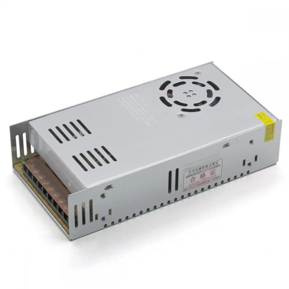
- Install the supply inside an enclosure or compartment that prevents contact with mains voltage without blocking its fan or ventilation slots.
- Connect line to L, neutral to N and protective earth to the marked terminal; bond the metal enclosure to protective earth.
- Use a suitable fuse, switch, strain relief, terminal cover and physical separation between AC and DC wiring.
- Size cables and terminals for actual current, length, temperature and voltage drop; protect individual branches where appropriate.
- Use a multimeter to verify voltage, polarity and terminal tightness before connecting electronics.
- Do not confuse -V with protective earth and do not open the supply: its capacitors may retain energy after disconnection.
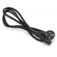
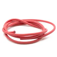
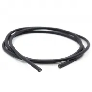
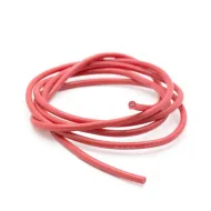
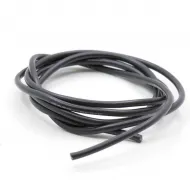
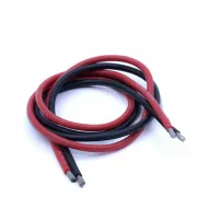
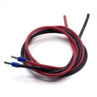
A mains input can use the IEC C14 inlet with switch and fuse holder and the Schuko to IEC C13 cable, provided the assembly and fuse are correctly rated. For high-current DC branches, we stock red 12 AWG flexible silicone cable and black 12 AWG flexible silicone cable; the final conductor size must be validated for each installation.
This is for you if
- Your load operates at 36 V DC and its total demand remains within the calculated margin.
- You want to create a TMC2240 MOTOR_POWER rail on an Octopus Pro and can verify jumpers, voltage and transients.
- You need a fan-cooled supply for motors, CNC, automation or a correctly designed electronic project.
- You can provide an enclosed, earthed, protected and adequately cooled installation.
This is not for you if
- You intend to power a 12 or 24 V controller, heaters, fans or accessories directly.
- You need to use TMC2240 drivers without checking or leaving any margin below their 36 V limit.
- You require a sealed, fanless or laboratory supply, or a battery charger.
- You do not have the knowledge or qualified assistance required for mains-voltage work.