

- Stock: 27
- Model: Mosfet25A-Modulo
Model:

1A

25A

30A

30A Fysetc
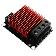
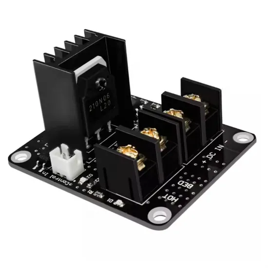
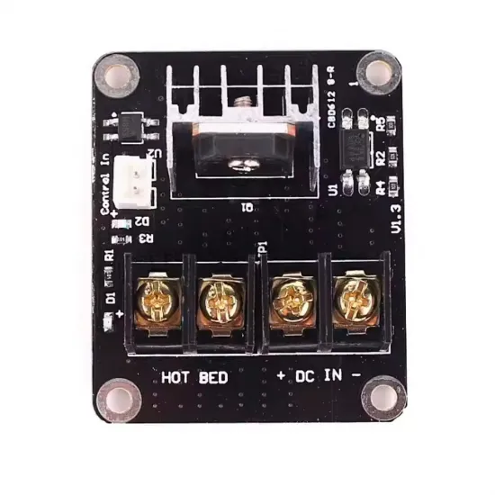
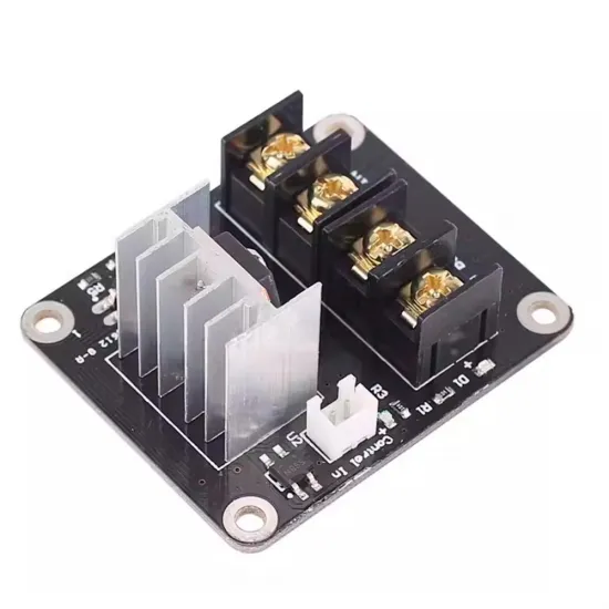
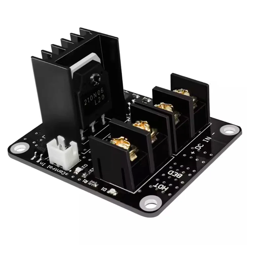
V1.3 external MOSFET module designed to switch a 12 or 24V DC heated bed or another resistive load from a controller board's heater output. The control input is separate from the power terminals and the power transistor has its own heatsink.
It is particularly useful where heated-bed current should not pass directly through the controller's terminal and built-in power stage, provided the supply, wiring, terminals, protection and cooling are correctly sized.
Main specifications
| Type | External MOSFET stage for resistive DC loads |
|---|---|
| Visible revision | V1.3 |
| Load voltage | 12 or 24V DC; 24V maximum |
| Advertised current | Up to 25A nominal, subject to cooling and installation |
| Control input | Polarised Control In with optocoupler |
| Power | DC IN for supply and HOT BED for load |
| Dimensions | Approximately 60 × 50 × 31mm |
| Contents | 1 MOSFET module |
Connection
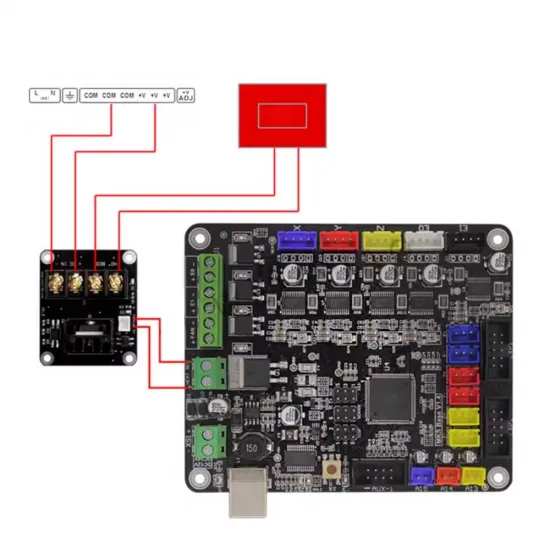
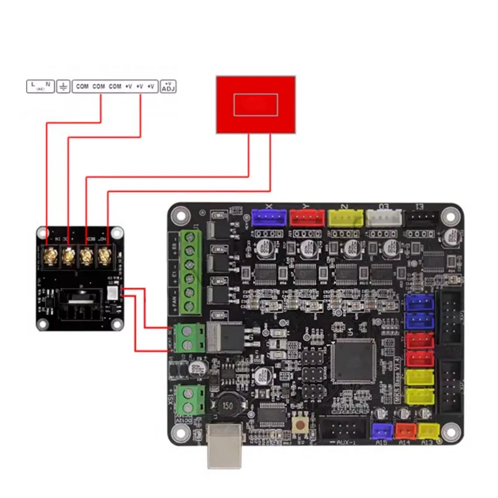
- Connect a 12 or 24V DC supply to
DC IN +/−. - Connect the heated bed or resistive load to the
HOT BEDterminals. - Connect the controller's heated-bed output to
Control In +/−, observing polarity. - Before applying power, check continuity, polarity and the absence of short circuits.
The Control In input is intended to receive the command from a heater output. Because visually similar V1.3 modules are advertised with conflicting signal ranges, do not connect it directly to a 3.3 or 5V GPIO without measuring the signal and confirming the exact revision.
How it works
The controller retains the temperature sensor, target and PWM signal. The module uses that signal to switch the main current from the supply to the load, reducing current through the controller's built-in power stage.
It is not a DC-DC converter or power supply: supply voltage must match the bed's rated voltage. It also does not replace the thermistor or firmware thermal protection.
Actual current and wire selection
The 25A figure is an advertised nominal maximum. It must not be read as a continuous-current guarantee at any temperature, airflow or wiring condition. The practical limit depends on every component in the current path, including the terminals, PCB, solder joints, transistor, heatsink, wire, ferrules and fuse.
Calculate a resistive load's current using I = P / V. A 240W bed supplied at 24V draws approximately 10A. The 235 × 235mm, 24V MK3 aluminium heated bed and the pre-wired version are examples of 240W loads whose complete installation must be sized for their nominal 10A current.
Installation and safety
- Disconnect power before installation, inspection or retightening.
- Use correctly sized wire, compatible ferrules and a fuse selected to protect the load and wiring.
- Do not tin stranded wire ends that will be clamped in screw terminals.
- Secure the module through its four mounting holes on a non-conductive support and provide airflow around the heatsink.
- Prevent moving bed wiring from stressing the terminals by adding strain relief.
- Check temperature, tightness, smell and discolouration during the first heating cycles.
- Keep thermal-runaway protection enabled. An independent thermal fuse may be added when its current, temperature and mounting suit the application.
- If the bed heats without a command, disconnect power immediately.
It is intended exclusively for low-voltage direct-current loads. Do not connect it to mains voltage or use it as a replacement for an AC SSR or contactor.
Firmware: Marlin, Klipper and RepRapFirmware
When the same bed output is retained, the module needs no new pin and does not change the sensor type. Firmware continues to control the bed as before.
- Marlin: when bed PID tuning needs to be repeated, use
M303 E-1 C8 S60and save the result according to the firmware version and EEPROM configuration. - Klipper: use
PID_CALIBRATE HEATER=heater_bed TARGET=60, followed bySAVE_CONFIG. - RepRapFirmware: if the bed is heater 0, use
M303 H0 S60, review it withM307 H0and transfer the values toconfig.g.
The temperature shown is an example. Verify the sensor, output shut-off and thermal protection before autotuning, and supervise the machine throughout the test.
Compatibility
Conditionally compatible with 12 or 24V 3D printers—including RepRap/RAMPS architectures, Prusa i3 derivatives, Anet, Creality and custom machines—when load voltage, current, heated-bed output type and voltage, polarity, mounting space, wiring and cooling all match. Revisions of the same printer can use different connections, so the model name alone cannot guarantee compatibility.
If the specific four-wire BIQU116-A2 layout is required, see the BIQU116-A2 30A MOSFET module. A branded alternative is the FYSETC MOSFET module for 12/24V loads.