

- Stock: 18
- Model: UPS-24V

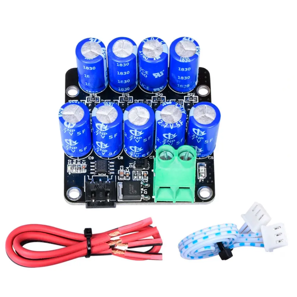
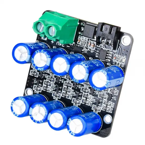
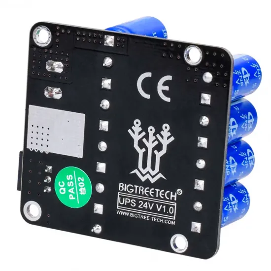
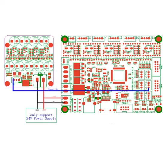
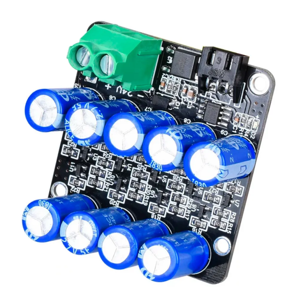
The BIGTREETECH UPS 24V V1.0 is a power-loss detection and recovery module for 3D printers operating exclusively from 24V DC. When the main supply disappears, it signals the controller board and uses the energy stored in its supercapacitors to keep the electronics powered for a short time.
This reserve allows a correctly configured firmware to save the print state, disable electrical loads and, when the mechanics and available energy permit, raise or move the nozzle away before the machine stops.
Important: this is not a conventional long-runtime UPS and it is not designed to keep the printer running during an outage. Its purpose is to provide a short reserve for a controlled shutdown and subsequent print recovery.
How it works
- During normal operation, the module remains connected to the 24V rail and charges its supercapacitors.
- When the power supply fails, the detection output changes from low to high level.
- The controller must detect this signal through a compatible PWR-DET input or GPIO.
- The firmware switches off the heaters, saves the print state and performs the configured safety movement.
- When power returns, the firmware may offer print recovery if the printing workflow supports it.
The available runtime depends on the connected electronics, commanded movements and condition of the supercapacitors. The manufacturer does not specify a fixed runtime, so every installation must be validated with a supervised test.
Technical specifications
| Manufacturer | BIGTREETECH / BIQU |
|---|---|
| Model | BTT UPS 24V V1.0 |
| Supply voltage | 24V DC only |
| Declared logic voltage | 3.3V or 5V |
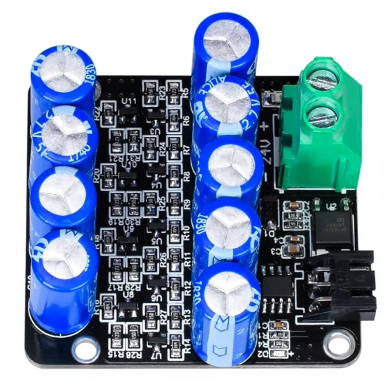
| Energy storage | 9 × 2.7V, 5F supercapacitors |
| Detection circuit | LM393 voltage comparator |
| Normal signal state | Low |
| Power-loss signal state | High |
| Signal connector | 3-position XH2.54: S, NC and NC |
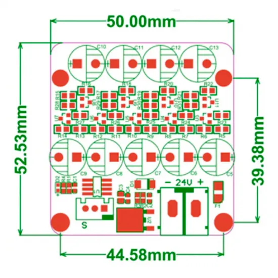
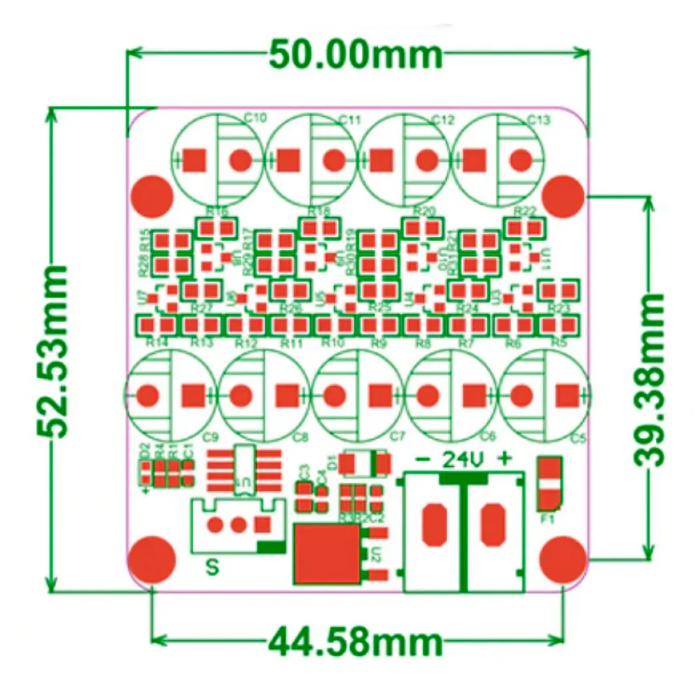
| Dimensions | 52.53 × 50mm |
| Mounting-hole spacing | 44.58 × 39.38mm centre-to-centre |
| Indicator | Red D2 power LED |
| Protection | Input reverse-polarity protection |
Compatibility
The module can be used in a 24V 3D printer when its controller provides a suitable power-loss detection input and its firmware can save and recover the print state.
BIGTREETECH documents this function on boards such as the BIGTREETECH SKR 3 and BIGTREETECH Octopus, as well as on other SKR boards. Always verify the exact board revision, pinout and firmware configuration.
A 24V supply alone does not guarantee compatibility. Some printers may require custom firmware compilation, wiring changes or a different GPIO input. The module is not suitable for 12V or 48V systems or for controllers unable to process a power-loss signal.
Wiring
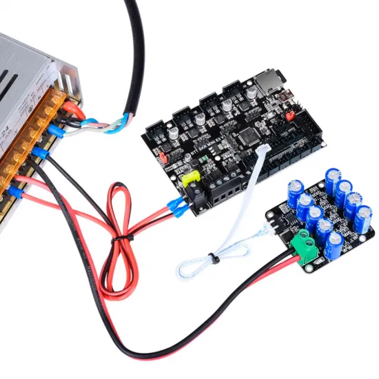
- Connect the power terminal in parallel with the 24V PSU output, observing the +24V and GND markings.
- Connect pin S to the board's appropriate PWR-DET input or GPIO.
- The other two positions are marked NC and must remain unconnected.
- Never determine the pinout from wire colours or connector shape alone.
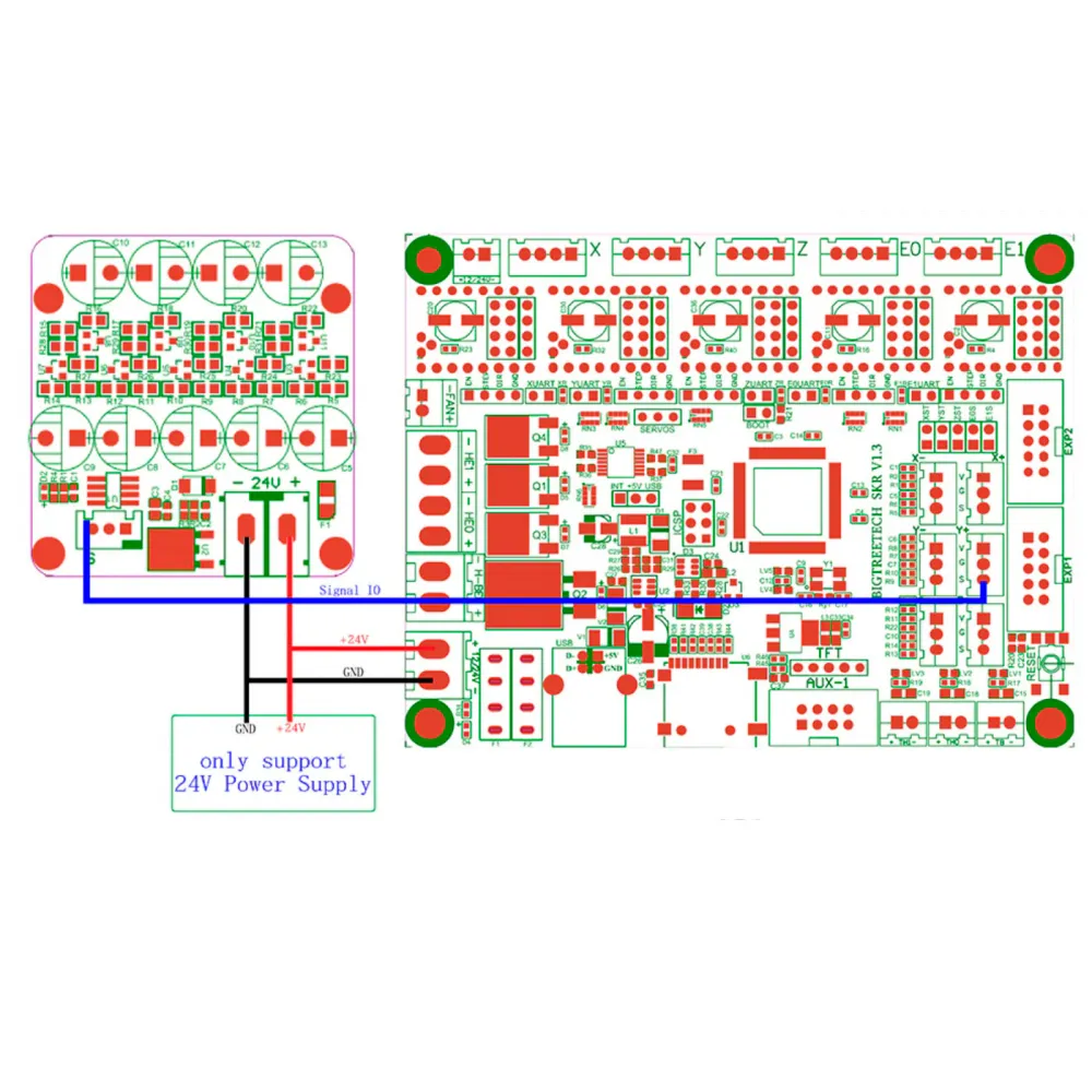
The diagram above is a specific SKR V1.3 example. Connector position and GPIO assignments vary between boards and revisions.
Marlin configuration
Marlin provides dedicated power-loss recovery functions. The following options should be reviewed when compiling the firmware:
#define SDSUPPORT
#define POWER_LOSS_RECOVERY
#define PLR_ENABLED_DEFAULT true
#define BACKUP_POWER_SUPPLY
#define POWER_LOSS_STATE HIGH
POWER_LOSS_PIN must be assigned to the actual GPIO used by the controller. The correct pull-up or pull-down and a safe POWER_LOSS_ZRAISE value must also be selected for the machine.
After installing the firmware, power-loss recovery can be enabled and checked with:
M413 S1
M500
M413
M500 stores the setting when EEPROM support is enabled. Marlin recovery is mainly intended for prints read from a compatible SD card or local storage. Exact behaviour may vary with the Marlin version, display and controller configuration.
Using the module with Klipper
Klipper does not provide a universal equivalent to Marlin recovery following a complete power failure. The module may be used as a digital input for a custom shutdown procedure, but this requires the host and MCU to remain powered, the correct GPIO to be selected and a machine-specific macro or service to be developed.
The module alone does not guarantee that a Raspberry Pi, BTT Pi or other host can preserve and recover the complete print state. Every Klipper integration must be designed and tested for the particular printer.
Using the module with RepRapFirmware
The signal may be incorporated into a custom emergency procedure on some RepRapFirmware-compatible boards, but there is no universal wiring or configuration file. The supported input, signal level, controller revision and recovery procedure must be checked for the firmware version being used.
Safe installation and testing
- Make all connections with the power supply disconnected.
- Mount the PCB on insulated spacers and prevent contact with metal surfaces.
- Configure immediate bed and hotend shutdown first.
- Confirm that the controller detects the signal before enabling backup-powered movement.
- Perform the first simulated outage under supervision and without a valuable print.
- Confirm that state saving and movement finish before the stored energy is exhausted.
Caution: the supercapacitors may remain charged after the PSU is disconnected. Wait for the LED to turn off and verify that voltage has fallen before handling the module. Do not short the terminals to discharge it.
Package contents
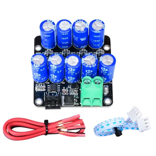
- 1 × BIGTREETECH UPS 24V V1.0 module.
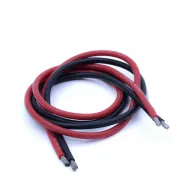
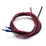
- 1 × red and black power cable.
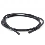
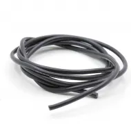
- 1 × signal cable.