

Print the same model on the same machine with the same nozzle and you can still get two different top surfaces. On one, the lines barely touch. On the other, the nozzle drags across ridges of excess plastic. The difference may come from how the extruder feeds the filament, how much material the slicer requests, or how much the hotend can melt once the print speeds up.
At HTA3D, we check how far the extruder moves the filament and how much material the print needs as separate questions. The distinction helps make sense of gaps in a top surface, an unexpected feed measurement and even a part that looks sound but leaks.
Go to a section
From filament to printed lineTest preparationExtruder feedTemperatureOrcaSlicer flow ratioVolumetric flowCorners and retractionTroubleshootingWorkshop checksValidationCommon questionsReferencesFrom filament to a printed line
The extruder moves a length of filament. The volume that enters the hotend depends on the filament's cross-sectional area, which increases with the square of its diameter. For the same length, 1.78 mm filament contains about 7% more material than 1.72 mm filament. The figures illustrate the effect of a small change in diameter. Tolerances depend on the particular filament.
At the nozzle, each printed line has to fit between its neighbours. Too little material can leave gaps. Excess plastic can rise above the surface or push the outline outwards. This is why differences in feeding can affect both the visible finish and the contact between lines inside the part.
Marlin's E-steps and Klipper's rotation_distance describe how the extruder moves filament. The flow ratio scales the amount the slicer requests for a given path. A factor of 1.00 uses the profile reference. A factor of 0.98 requests 2% less, and 1.02 requests 2% more. A new spool usually calls for a check of the filament profile. A motor or gear change, or a repeatable feed error, warrants a check of the machine configuration.
Set up a test you can repeat
Calibration depends on a consistent supply of filament. A spool that catches, a drive gear that leaves dust or a partial clog can produce different readings in otherwise identical tests. A correction based on one of those readings may make the next print worse. The guide to FDM clogs helps trace where the resistance starts.
- Duplicate the profile and record the machine, extruder, nozzle, filament and batch if known. Use the same spool throughout the test and follow the filament maker's drying instructions.
- Check that the spool turns freely, the gears grip the filament and the first layer prints correctly. If the defect only affects the base, check bed cleanliness, levelling and Z height before using that sample to judge flow.
- Use a suitable temperature and moderate speed when comparing material quantities. Note any flow correction active on the printer. Save the 3MF and identify the samples before lifting them off the bed.
For a new profile, OrcaSlicer recommends setting temperature, maximum volumetric flow, pressure advance, flow ratio and retraction in that order, once feed is stable. On a well-configured machine with a new spool, start by checking temperature and flow at a moderate volumetric rate. Recheck the top surface if you make a substantial change to temperature, pressure advance or printing speed.
How far the extruder moves the filament
If you request 100 mm and measure 95 mm several times, you can calculate a correction. If you measure 95 mm on one attempt and 100 mm on the next, find where the filament slips or meets resistance. A single reading can look the same in both cases, so repeating the measurement matters.
New extruder assembly: calculate a starting value
Start with the documentation for the exact extruder revision. To calculate from the hardware, use the motor's full steps per revolution (200 for 1.8° or 400 for 0.9°), the configured microsteps, the number of motor turns per turn of the final drive wheel and the effective diameter where the teeth move the filament. That diameter can differ from the visible outside diameter.
Let S be the full steps per revolution, M the microsteps, G the reduction and D the effective diameter in millimetres. Then steps/mm ≈ S × M × G ÷ (π × D). With gear_ratio declared, Klipper's rotation_distance describes the feed per turn of the final drive gear (≈ π × D). With the reduction included in rotation_distance and no separate gear_ratio, it describes the feed per turn of the motor (≈ π × D ÷ G).
A 7 mm effective wheel and a 5:1 reduction give two ways to describe the same assembly: 21.991 mm with gear_ratio: 5:1, or 4.398 mm with the ratio omitted. Choose one representation so the reduction is applied once. Use actual tooth counts if available, since advertised ratios may be rounded. The examples and presets give you a starting point to check on your machine.
Find a starting point for your extruder
Select your exact revision or use the editable example. Published values are starting points. Measure actual feed on your setup.
When converting published steps/mm, use the full-step count for the reference motor. If yours differs, start from a physical distance or the drive geometry. In the firmware configuration, use a decimal point and omit thousands separators. Nominal gear ratios may be rounded.
The formulas and model references are also available separately.
View the reference for each model
- Orbiter V2.0 · LDO · Orbiter Projects lists 690 steps/mm at 1/16 microstepping and 4.69 mm without gear_ratio. Converting E690 gives 4.638 mm. These are separate references.
- Orbiter V2.5 · LDO · Orbiter Projects lists 4.69 mm and LDO lists 4.637 mm. Both list E690 at 1/16 microstepping. The designer's value is loaded. Enter 4.637 mm to compare.
- Smart Orbiter V3 · LDO · The designer lists E690 at 1/16 microstepping and a Klipper example using 4.69 mm without gear_ratio. Converting E690 gives 4.638 mm.
- HTA3D direct MK8 + V6 · P3Steel · HTA3D's historical reference for a 1.8° motor and direct drive is 152 steps/mm at 1/16 microstepping. The product page rounds the equivalent distance to 21.05 mm.
- HTA3D V2 dual drive · 3DSteel · Direct 1:1 transmission. HTA3D's reference is 140 steps/mm at 1/16 microstepping. The published equivalent distance is 22.86 mm.
- FYSETC Sherpa Mini V1.5 · 8-tooth pinion · E870 is FYSETC's starting point for this revision. The HTA3D example uses a 1.8° motor and 16 microsteps. Confirm the 8-tooth pinion. Rotation distances are calculated.
- Trianglelab TBG-Lite Right · 36 mm LDO · Trianglelab lists E615 at 1/16 microstepping and an 11.53125:1 reduction. The distances are calculated for the 1.8° motor in this version.
- Trianglelab TBG-Air · LDO and V6 hotend · Trianglelab lists nominal E446.9 at 1/16 microstepping and an 8.44:1 reduction. Distances are calculated for 200 full steps per revolution.
- BIQU / BigTreeTech Nebula · 11.25:1 · BigTreeTech lists 51.75 mm with gear_ratio: 11.25:1. The calculated equivalent without a separate gear_ratio is 4.60 mm.
- FYSETC Metal Sherpa Mini V1.5 CNC · template · The current product page lists a 36 mm Moons motor, 8-tooth pinion and 6.25:1 reduction. Confirm the motor, microstepping and drive before transferring E870 from the printed Sherpa.
- Fresa 3D HGX Lite without motor · template · The stated reduction is approximate. Enter the motor, microstepping and effective diameter for your own setup.
Measuring free feed in the HTA3D workshop
When assembling or modifying a printer, we sometimes separate the extruder from the hotend to measure the feed on its own. This shows how the gears behave before adding resistance at the nozzle. We use a rigid filament, preferably light in colour so the mark is easy to see. Prepare the machine according to its procedure. If the filament cannot exit safely, use the heated test. Avoid pushing filament through an assembled cold hotend or disabling its protections.
- Mark the filament and measure from a fixed point beside the extruder. Check the direction with a short, slow move.
- Request a known travel distance, such as 100 mm if the machine allows it. Subtract the remaining distance to the mark from the starting distance. Repeat under the same conditions.
- If travel is about half or twice the requested amount, check the motor's full-step count, microsteps, reduction and driver. For a moderate, repeatable error, calculate a correction and measure again after applying it.
Measuring slow feed through a heated hotend
The Klipper procedure keeps the hotend assembled. Feeding slowly reduces the resistance involved in pushing a large amount of plastic through the nozzle in a short time. The result describes feed under those conditions and can differ from a free-feed measurement.
- Identify the active extruder and back up its configuration. Heat the hotend to a suitable temperature for the filament and wait for it to stabilise. Leave room beneath the nozzle and keep the machine's protections active.
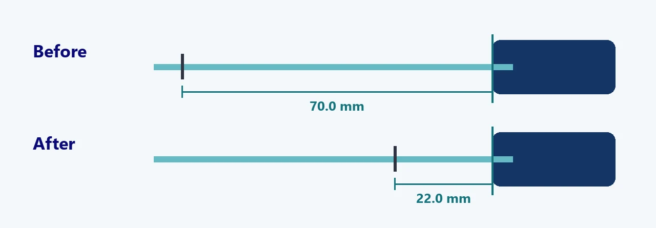
- Mark the filament about 70 mm from the inlet and measure the exact distance. Request 50 mm at 1 mm/s. The documentation uses
G91andG1 E50 F60. Check your machine's motion and extrusion modes before using those commands and restore them afterwards. Avoid controls that leave you unable to set the feed speed. - Measure the remaining distance from the same point. If the mark moves from 70.0 to 22.0 mm away, the extruder has fed 48.0 mm. Repeat the test. If the extruder slips or skips steps, stop the test. If the readings vary between attempts, find the cause before editing the firmware. Klipper recommends repeating the test if the discrepancy exceeds about 2 mm.
Correcting and saving the feed settings
Marlin: new steps/mm = current steps/mm × requested travel ÷ measured travel. If a machine set to 400 steps/mm moves 95 mm when asked for 100 mm, the calculation gives 421.05 steps/mm. Read the current setting with M92 without parameters or M503, depending on the installation. An example of writing the value is M92 E421.05. Confirm which extruder is active. Test the temporary value and use M500 if EEPROM is enabled. Check the saved setting after restarting.
Klipper: new rotation_distance = previous distance × measured travel ÷ requested travel. Starting at 7.50 mm and measuring 95 mm for the same request of 100 mm gives 7.125 mm. A shorter rotation distance tells the firmware that it needs more turns to feed the requested length. Edit the active section in printer.cfg, keep the same gear_ratio representation and measure again after restarting.
In Marlin, check whether M221 applies an additional flow percentage. When volumetric extrusion is active through M200, E is in mm³. For a test based on filament length, check the units and extrusion mode before requesting movement. Keep the original settings so you can restore them.
Calculate the feed correction
Choose a setting. Each option loads an editable example. The calculator accepts a decimal point or comma.
Use the formulas and examples in the guide if the calculator is unavailable.
What temperature changes
Within the material's working range, molten polymer usually flows more readily as it gets hotter. This can help layers bond and can also change how much plastic oozes during a travel move. Two surfaces can have different gloss even when they received the same amount of material.
Compare temperatures within the limits specified for the filament and printer. With an OrcaSlicer temperature tower, check that each segment prints at the intended temperature. Keep speed, layer height and cooling constant where you want to compare. Look at walls, bridges, stringing and layer bonding in light of what the part needs to do. If a flexible filament deforms in a tall tower, use several low samples that are easier to compare.
How much material OrcaSlicer requests
OrcaSlicer's built-in test compares surfaces printed with different flow ratios. A single-wall cube compares a printed measurement with the line width set in the profile. The OrcaSlicer plate is a direct way to select a flow ratio from the surface finish. The cube offers a second check and helps explain how a wall takes shape. For both tests, work within a volumetric rate the printer can already sustain.
OrcaSlicer: the YOLO plate
- Select the printer, filament and process you will actually use. Record the starting flow ratio and choose the YOLO flow ratio test, if available. The standard documented test makes eleven samples from −0.05 to +0.05 in steps of 0.01.
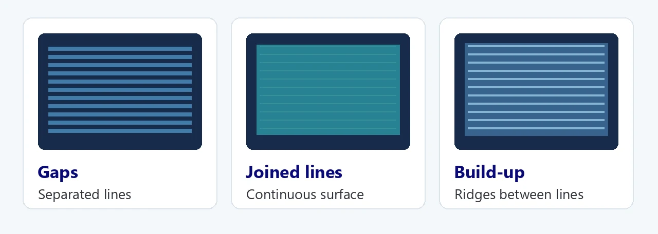
- Look at the middle of the top surfaces under light from the side. Check how the arcs meet the inner area and look for joined lines with few gaps or ridges. Judge several areas away from an isolated corner or seam.
- Add the signed modifier to the starting value. If the best sample is +0.01 and you started at 0.98, save 0.98 + 0.01 = 0.99. If zero looks best, the starting value may already work. If one end of the range looks best, check feed and temperature before deciding whether to centre a new test on another value.
OrcaSlicer: the classic two-pass test
Here the labels are percentages. Use new ratio = previous ratio × (1 + modifier ÷ 100). If you start at 0.98 and choose +5 in the first pass, save 1.029 before generating the second. If you then choose −2, use 1.029 as the starting value and obtain 1.00842. The classic +5 and YOLO's +0.05 call for different calculations.
Save the absolute value under Flow ratio in the filament profile. Enter 0.99 if that is the result. Start a clean project and select the saved profile so the test plate's modifiers stay out of the verification print. Check whether the printer display or firmware applies another correction.
Calculate the flow ratio
Choose a setting. Each option loads an editable example. The calculator accepts a decimal point or comma.
Use the formulas and examples in the guide if the calculator is unavailable.
Single-wall cube
Prepare a cube about 20 × 20 × 20 mm, with one wall, no top or infill and enough base to hold it down. Vase mode uses a continuous path and a normal perimeter can have a seam. Check the line width in the preview. For a 0.4 mm nozzle, 0.50 mm is one example if the profile supports it. With a 0.6 mm nozzle, 0.70 or 0.80 mm are examples to check against your profile.
Once the cube has cooled, measure the centre of all four faces at the same height, away from corners, seams and the first few layers. Use light, consistent pressure with the callipers. If you measure 0.49, 0.50, 0.51 and 0.50 mm, the mean is 0.50 mm. If the faces vary substantially, check the toolpaths and how you are measuring before calculating a correction.
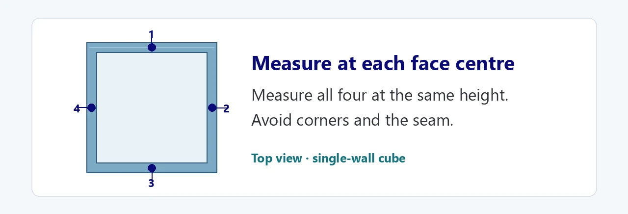
As an estimate, new ratio ≈ previous ratio × target width ÷ mean wall thickness. With a starting ratio of 1.00, a 0.50 mm target and a 0.51 mm mean, the result is about 0.9804. The shape and texture of the printed line affect the thickness the callipers measure. Check the result on a top surface and a representative part. To correct E-steps or rotation distance, use a filament feed measurement.
Compare the four walls
Enter the readings in millimetres. The result is an estimate. Check it against a top surface test.
To calculate by hand, add the four readings, divide by four and apply the formula above.
How much material can flow per second
If the width and height of a line stay the same, doubling the printing speed calls for roughly twice the volume per second. The slicer estimates this demand for each path. The hotend transfers heat to the filament as it passes through. At a higher flow rate, the filament spends less time in the melt zone. A top surface can print well at moderate speed and a long straight line can thin out when the demand exceeds what the assembly can sustain.
Using a rectangular approximation, flow rate ≈ line width × layer height × speed. At 100 mm/s, a line 0.45 × 0.20 mm calls for about 9 mm³/s. A line 0.60 × 0.28 mm at the same speed raises the estimated demand to 16.8 mm³/s. Read the planned rate in the slicer preview and use a printed test to find out whether the hotend can sustain it.
- Slice a maximum volumetric flow test with your working nozzle, temperature and spool. Start within a range that already prints consistently. Check the preview to see that demand rises despite speed limits or cooling slowdowns.
- Find the first repeatable thinning, broken lines, weak layer bonding or skipped feed. A change in sheen on its own calls for a closer look. Match the height of the defect to the flow rate in the preview for that layer. If the entire test prints well, the final rate tells you how far the test reached.
- Allow some headroom below the first sign of deterioration. If it starts at 12 mm³/s, a 15% reduction gives 10.2 mm³/s as an initial cap. Save it under Max volumetric speed and check a representative part, especially long, wide lines.
Why a corner can bulge when the straight lines look clean
As the print head slows to turn, the path needs less material per second. Nozzle pressure takes time to fall, partly because the feed system has some elasticity. Plastic can keep coming out while the head moves a shorter distance, building up at the corner. Klipper's Pressure Advance and Marlin's Linear Advance compensate for that response with settings specific to each firmware.
Print a compatible pattern at a stable volumetric rate. Compare several corners away from the seam. Too little compensation may leave a bulge. Too much can leave a thin corner or a gap. Save the setting where your firmware applies it and check that the start G-code leaves it in effect. In Marlin, M900 sets Linear Advance when enabled. Verify the result at your working acceleration.
Residual pressure and temperature can also leave strings during a travel move. To check retraction, use dry filament and a stable temperature. Change distance and speed in separate tests. Look for a setting that reduces stringing and leaves the first line after travel continuous.
What the location of a defect can tell you
| Where it appears | What to compare |
|---|---|
| Only on the first layer | Bed cleanliness, levelling and Z height. A sample several layers thick helps distinguish the base from the top. |
| Across the top surface at moderate speed | Steady feed, possible partial clog, infill support and flow ratio samples. |
| On long straight lines as the head speeds up | Planned volumetric flow. Try the same geometry and spool with a lower cap. |
| At corners or after a travel move | Pressure advance if it happens while slowing. If it happens when printing resumes, compare temperature, retraction and filament condition. |
| In feed readings that change between attempts | Filament path, gear grip, spool and hotend resistance. Repeat once the feed is steady. |
| Where parts fit together, with clean surfaces | Clearance, orientation and shrinkage. A fit sample can help identify the adjustment. |
If the diagnosis points to a component, confirm the revision and dimensions of the replacement. For a nozzle, check the family, thread and length. For a complete hotend, also check the filament diameter, voltage and sensor where applicable. Browse assembled hotends if you need to compare complete assemblies.
What a clean surface can hide
In a narrow wall or a solid part, excess plastic between neighbouring lines has little room to go and can push the outline outwards. A sparsely filled area has more space inside, though top surfaces and perimeters can still be affected. With too little plastic, contact between lines can shrink and gaps can form. The consequences depend on the orientation, material and purpose of the part.
At HTA3D, we made solid parts that had to hold water. Excess material left visible marks. With too little material, the part could have leak paths that were hard to see. We filled each unit with water and left it under observation for about a day. We rejected any unit that leaked. Looking at the surface showed visible excess material. The water revealed whether any gap formed a path from the inside to the outside.
When printing a batch of identical parts, weighing several on the same scale under comparable conditions can reveal changes that are hard to see. If the mass shifts, check the feed, material and profile. The part's function still needs its own test. With flexible materials, the drive gear can also deform the filament and change how it feeds. Even two TPU filaments of the same diameter may need different guidance, temperatures or volumetric limits.
Two ways to validate the settings
- Stable printer and a new spool. Check temperature and feed. Compare a flow ratio plate at a moderate rate, save the new spool's ratio and print a representative part.
- New or modified extruder. Start with the model's documentation, measure feed, correct a repeatable error and verify the new settings. Then tune the filament profile and check which compensations are active.
Record the machine, nozzle, spool and batch, temperature, flow ratio, volumetric limit, pressure advance, retraction and result. A 3MF file and a note about where a defect first appeared are useful when you return to a spool. If the part will bear a load or hold water, test a sample in the relevant orientation, assembly and conditions.
View or download the A4 calibration worksheet (PDF)
If you would like help with a defect, tell us the printer, nozzle, filament and where the problem appears. A photo of the sample and the test settings help us understand the issue. Contact HTA3D or see our technical support and consulting service.
Questions when applying the settings
What if the cube and the plate suggest different values?
Check the planned width in the preview and whether the wall readings are repeatable. The plate compares the finish and the cube estimates a correction from measured thickness. Validate the result on a part that represents the job.
When should I repeat the flow ratio test?
When a change affects deposition, such as a different spool, a substantially different temperature or a new combination of nozzle and volumetric flow. For a small adjustment, a good result on a representative part may be enough.
Technical references
- OrcaSlicer. Calibration guide, flow ratio and volumetric flow test.
- Klipper. Rotation distance and pressure advance.
- Marlin. Steps per unit, volumetric extrusion, flow percentage and Linear Advance.
Related Products

Leave a Comment