

SKR v1.3 Board connections - Quick guide
The world of 3D printing is in a moment of frenetic development, driven largely by the Maker community and the Open Source movement. One of the great advances made has been the adoption of 32-bit processors for the control of our 3D printers.
These 32-bit processors offer many advantages over 8-bit processors:
- Lower cost in large-scale productions.
- Greater processing capacity.
- Higher response speeds.
- Very superior ability to add new and powerful functions.
And a single disadvantage, the need to adapt a program initially designed for 8 bits. Luckily this is almost completed by the Marlin team, the Marlin versions today (2020) have very few bugs for some 32-bit processors.
Within all the 32-bit boards that have been released, the SKR 1.3 has many advantages that have made it a success:
- Low cost. Barely higher than the equivalent with Ramps.
- Excellent build quality for the price.
- 24v compatibility.
- More than enough connections for the vast majority of 3D printers, with the possibility of expansion to duplicate the motors of an axis from simple modules.
- All these advantages are also presented in a compact format that can be installed on many models of 3D printers without requiring any modifications.
CONNECTIONS:
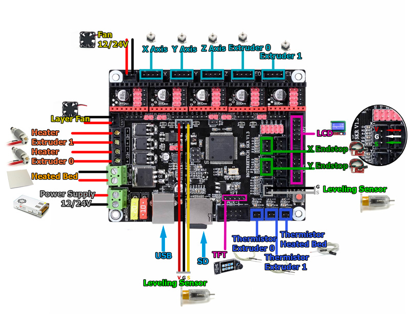
Power Supply:
The power supply provides power to our machine. We can use a 12 or 24 V source, choosing the corresponding components for the same voltage. The source feeds with a bipolar line to the connection, it is very important to connect the polarity correctly.
Resistences:
The connectios are:
HE0: Hotend 0 resistence (it hasn't polarity)
HE1: Hotend 1 resistence (it hasn't polarity)
H-BED: Heated bed (it hasn't polarity)
12/24V Fan:
Here we can connect the fan of the electronics or hotend (it has polarity, in case of incorrectly connecting it we could damage the fan).
This fan will always be on.
Layer fan:
It has polarity, in case of connecting it incorrectly we could damage the fan.
This fan will be controlled by the firmware.
Stepper motors:
This electronics requires four or five controllers depending on whether our 3D printer has one or two extruders. Being three for each of the three axes of the printer and another for each extruder. We can see its placement in the scheme next to the motor connection.
In the case of the Z axis, usually 3D printers use two motors, we only find a connector on this board. To connect two, we can use this module to connect two motors in parallel.
The order of the motor wiring must also be taken into account, which will depend on the model and the manufacturer.
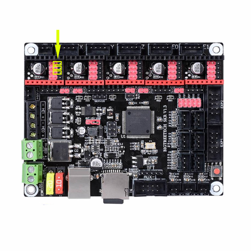
If we use STEP/DIR drivers such A4988 or DRV8825, we will have to place three jumpers on the pins as we see in the image:
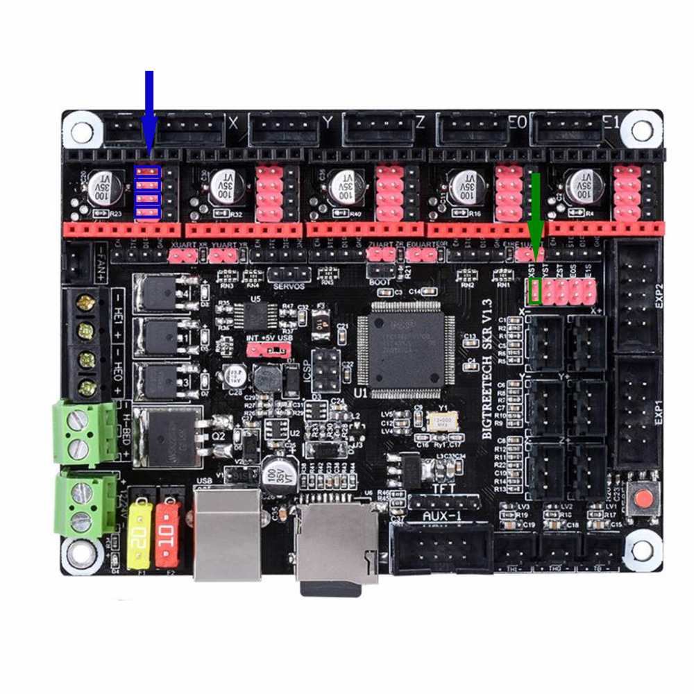
If we use SPI drivers, such as TMC2130 SPI, we will have to place jumpers on the left pins as we see in this case in the controller for the X axis. Also, if we are not going to use endstops since they are not necessary, we will have to put another jumper on the XST pins indicated with the green arrow (in this case example for the X axis motor).
Thus, we will connect the DIAG1 pin of the controller with the corresponding pin in the limit switch connection. It is important not to connect a limit switch on the axis where we have enabled this function since “Sensorless Homing” and physical limit switches cannot be used simultaneously.
If we are using UART drivers, such as TM2208, TMC2209 or TMC2225 we need to put a jumper on the pins for this connection of each controller we use. In this image we indicate the extruder pins:
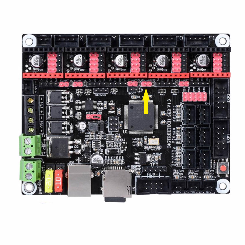
It will be only those jumpers that are used, jumpers are not put on the pins under the controllers.
Endstops:
Depending on the drivers we use, the limit switches will be necessary or not, since with the SPI communication the drivers will “know” when the printer skips steps and identifies this as the end of the route (well configured).
We can see the placement of the limit switch of X and Y. In the scheme we have located the connection for a configuration of Xmin and Ymin, if we want to configure it at the maximum, the connection is the one on the right as we can see that it is indicated in the board.
Z endstop would be located just below, but in this case we will use an automatic leveling sensor.
With the limit switches, it is very important that they are connected correctly, as if connected in reverse order will damage the board.
Auto leveling sensor:
The auto leveling sensor, as 3DTouch, has two connectios, one corresponds to the Z limit switch function and the other corresponds to the self-leveling function connected at the port for Servos.
To make the connections, simply for each cable or line we have to prepare the cable with the dupont connector.
As we can see, the black and white cable (signal) is connected in the position of the Zmin limit switch.
As the endstops, if we want to configure it for Zmax, it would be the right connection as we see indicated on the board.
The other cable is connected in the Servo position, in the order of the scheme (Signal, 5V, Ground).
Thermistors:
We can see in the diagram the position of the thermistors for Extruder 0, Extruder 1 and Heatedbed (they have no polarity).
LCD:
If we are going to use the usual screens (12864 or 2004), we will use the connection we see on the right in the scheme.
If we are going to use screens such as TFT24 V1.1 or TFT35 V3.0 we will have to use this connection for the touch function. If we want to use it with the Marlin interface, we just need the right connection. If we only want the touch interface, we only need the TFT connection. In order to change from one to another, we will have to connect both.
USB:
We can see its placement in the scheme.
SD:
We can see its placement in the scheme.
Modify the pin scheme:
As Marlin is completely open, we can swap the pins to for example control an additional fan if we are only going to use a fuser, etc. For this we can modify the file:
\ Marlin \ src \ pins \ lpc1768 \ pins_BTT_SKR_V1_3.h
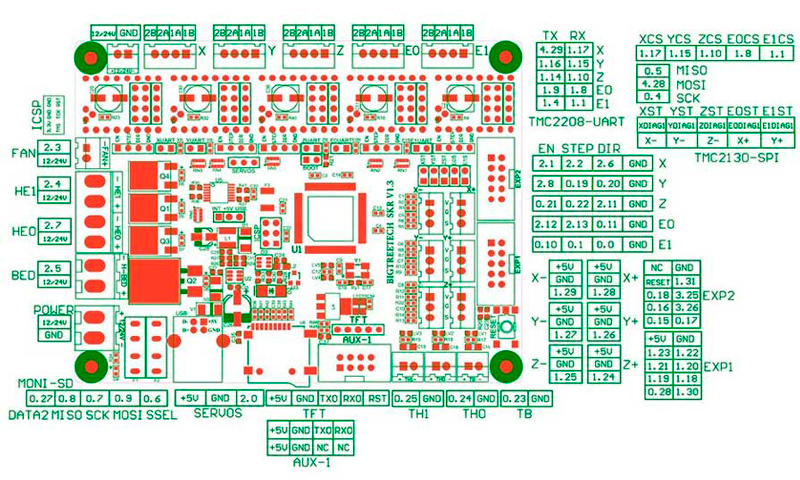
This image shows the position of all available pins on the board:
3 Comment(s)
Tenéis el Marlin? De este tipo de placas de 32bits para la p3 steel?
Próximamente tendremos una nueva 3DSteel con una placa 32 bits y su correspondiente firmware público :)
Thermistor Extruder 0, Extruder 1 are back to front on your marked up drawing?
Cheers Andrew
Very observant, thanks for pointing it out, it's true, the 0 and 1 are interchanged in the first drawing. The inscription on the plate is correct. Sorry for the inconveniences.
Can the SKR V1.3 have an additional potentiometer added to control the speed on four stepper motors in the case of controlling the feed rate on a cnc router?
Leave a Comment