

- Stock: 77
- Model: LCD-Cable-1m
Length

50cm
1m
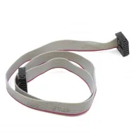
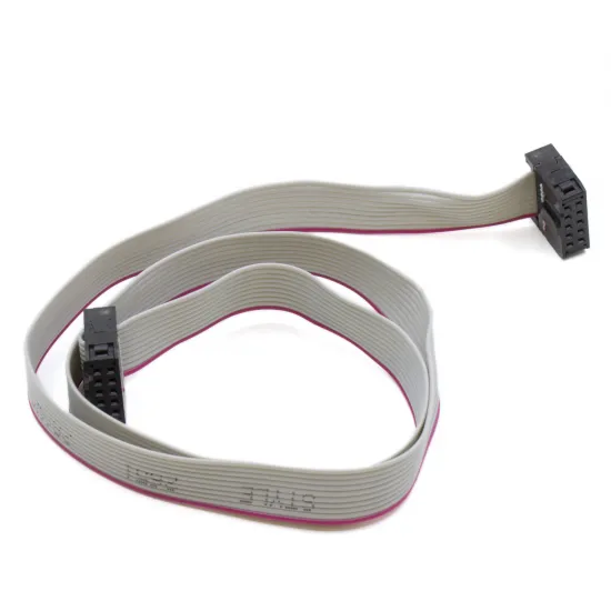
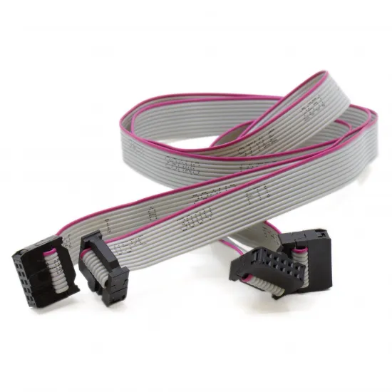
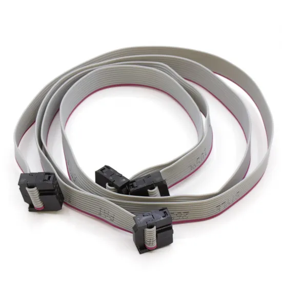
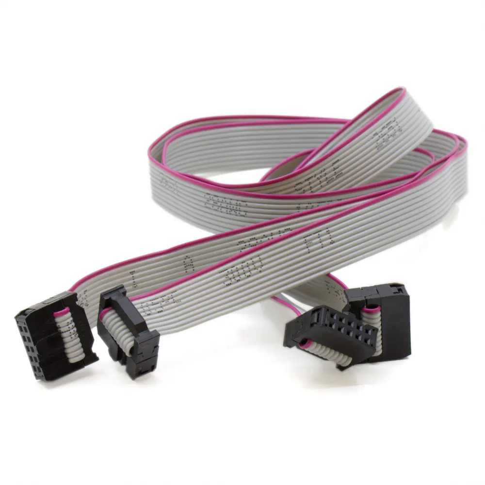
A pack of two 1 m flat ribbon cables with ten conductors and 2 × 5 female IDC connectors. It is intended for RepRap LCD displays that need simultaneous EXP1 and EXP2 connections to a compatible controller or adapter.
The one-metre length makes it easier to mount a display away from the electronics enclosure. Each AWM 2651 ribbon uses 28 AWG conductors and a red stripe identifying conductor 1 for orientation checks before power is applied.
Features
| Feature | Value |
|---|---|
| Cable type | AWM Style 2651 flat ribbon |
| Conductors per cable | 10 conductors, 28 AWG |
| Connectors per cable | 2 female 10-position IDC connectors in a 2 × 5 layout |
| Nominal connector pitch | 2.54 mm |
| Identification | Red stripe on conductor 1 |
| Length of each cable | 1 m |
| Ribbon voltage marking | 300 V |
| Contents | 2 cables |
EXP1 and EXP2 compatibility
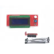
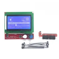
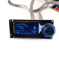
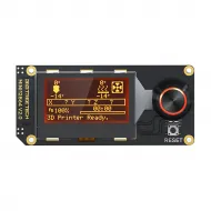
The pack can connect EXP1 and EXP2 together when both the display and controller share the same 2 × 5, 2.54 mm IDC format, pinout and orientation. This connector family is used by designs including the LCD 2004 Smart Controller, LCD 12864 Full Graphic Smart Controller and BIGTREETECH Mini 12864.
Two cables with matching connectors do not guarantee that every LCD is interchangeable. They are also unsuitable for HDMI, USB, FPC, DSI or proprietary display interfaces.
What the one-metre length changes
The additional length is useful for separate enclosures, large machines, external control panels and test benches. However, signals travel twice as far as with a 50 cm cable and can be more susceptible to interference or poor routing.
- Keep the ribbons away from motor, heater, heated-bed and power wiring.
- Do not coil them beside drivers or switching power supplies.
- Avoid sharp folds, pinching and abrasion against the frame.
- Secure the route without applying strain to the connectors.
- If the display shows corrupted characters, flicker or resets, first check orientation, continuity and routing.
Installation
- Fully power down and disconnect the machine.
- Identify EXP1 and EXP2 on both the display and controller or adapter.
- Compare pin 1, connector key and red stripe against the documentation or original cables.
- If no reliable reference is available, measure pin-to-pin continuity before installation.
- Connect each cable to the corresponding port without forcing the keys.
- Perform a supervised first start and disconnect power if the display does not initialise or any component heats up.
The 300 V figure belongs to the ribbon insulation marking. It must not be interpreted as an authorised working voltage for the complete assembly or permission to use it for mains wiring.
Firmware
The cables require no dedicated Marlin, Klipper or RepRapFirmware setting. The display must retain the configuration for its model and controller. A problem caused by cable length, interference or pinout cannot be solved with a generic firmware change.