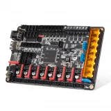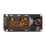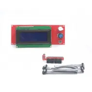
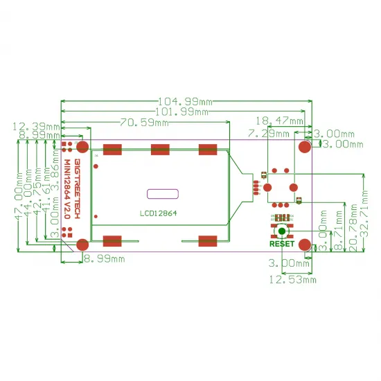


- Stock: 27
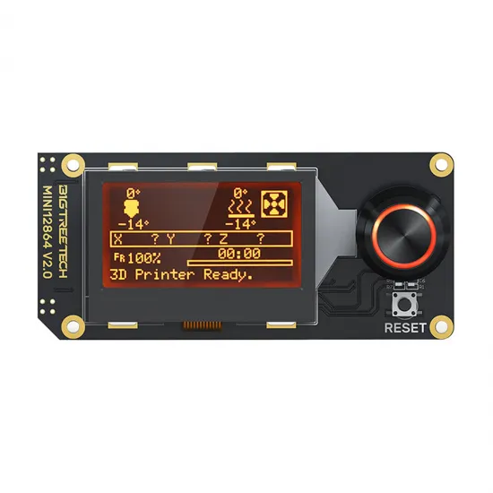
- Model: BTT Mini 12864 LCD

Model:

2004 LCD

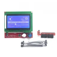
12864 LCD

Mini 12864 LCD - Fysetc

Mini 12864 LCD - BTT

Mini 12864 LCD - MKS
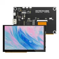
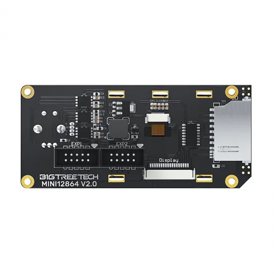
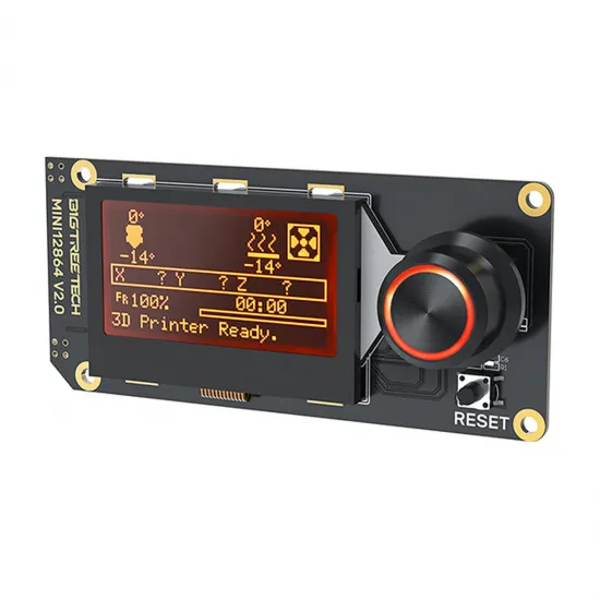
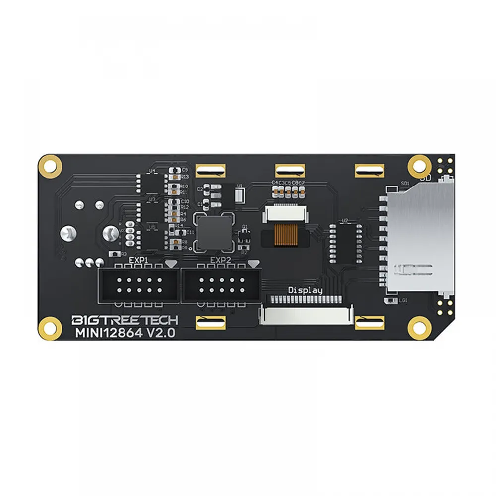
The BIGTREETECH MINI12864 V2.0 is a compact 128 × 64 graphic display for controlling compatible 3D printers and other machines directly through a rotary encoder. It integrates a full-size SD card reader, clickable encoder, reset button, beeper and three addressable RGB LEDs for the backlight.
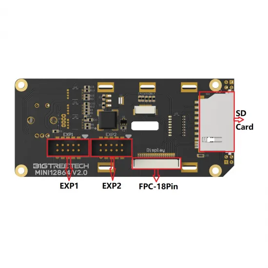
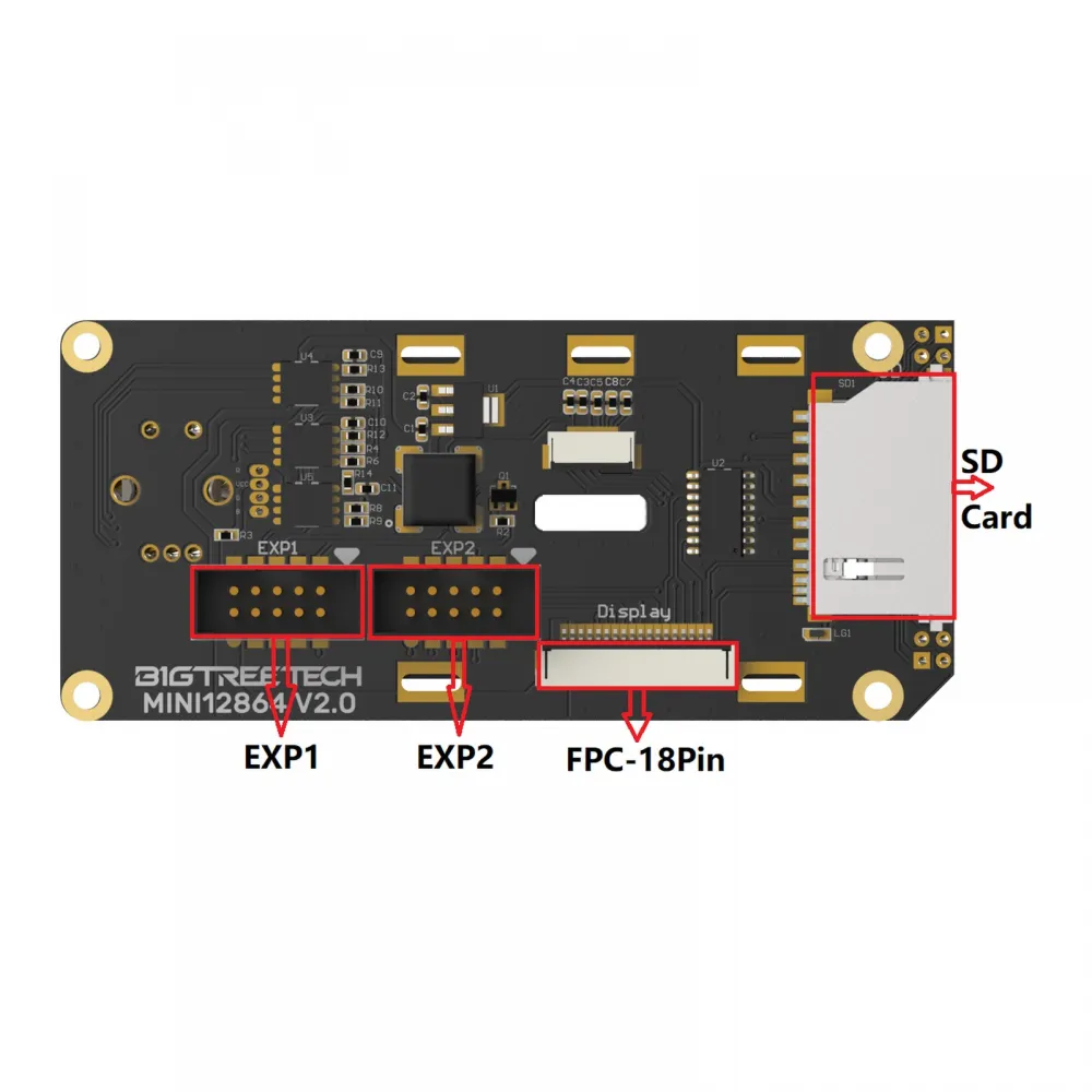
This V2.0 revision can communicate with the controller through the EXP1 + EXP2 headers commonly found on many RepRap electronics or through its 18-pin FPC connector. Matching connector shapes do not guarantee compatibility: power, pinout, orientation, controller board and firmware configuration must all match before installation.
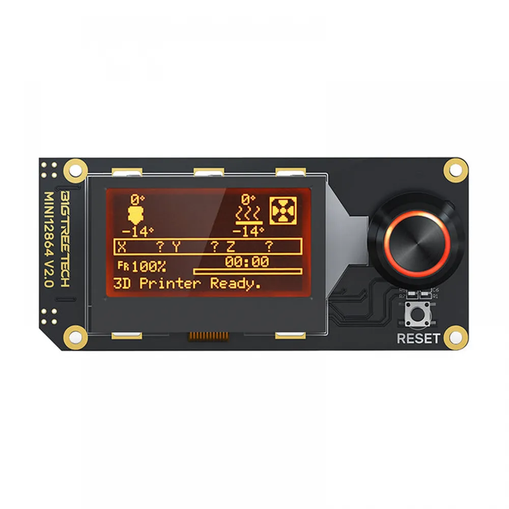
Main features
- 128 × 64 graphic LCD: displays menus, temperatures, position, progress and firmware-defined machine status.
- Clickable rotary encoder: scrolls through menus, changes values and confirms selections.
- Addressable RGB backlight: three LEDs configurable from supported firmware.
- Full-size SD card reader: operation depends on the controller and firmware having the SD signals connected and configured.
- EXP1 and EXP2: two 10-pin IDC headers for boards with a matching pinout.
- 18-pin FPC connector: a manufacturer-documented alternative for controller boards specifically designed for this connection.
- Reset and beeper: integrated reset button and audible indicator.
Technical specifications
| Feature | Value |
|---|---|
| Manufacturer and model | BIGTREETECH MINI12864 V2.0 |
| Type | Monochrome graphic LCD with RGB backlight |
| Resolution | 128 × 64 pixels |
| Commercial size | Approximately 2.4 inches |
| Firmware controller type | UC1701 |
| Power input | 5 V DC |
| SD card logic | 3.3 V and 5 V according to the manufacturer |
| Interfaces | EXP1 + EXP2 or 18-pin FPC |
| Controls | Clickable encoder and reset button |
| Lighting | 3 addressable RGB LEDs, RGB order in the official configuration |
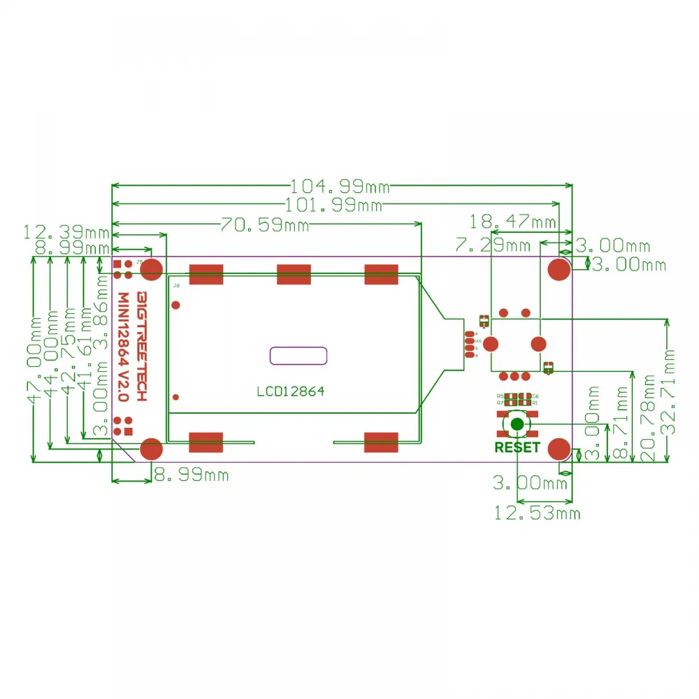
| Overall dimensions | 104.99 × 47 mm |
| Mounting centres | 93 × 41 mm |
| Mounting holes | 4 × Ø3 mm |
| Documented firmware | Marlin and Klipper; RepRapFirmware depends on board and wiring |
Connectors and signals
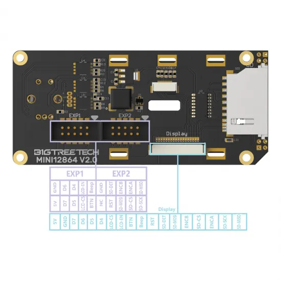
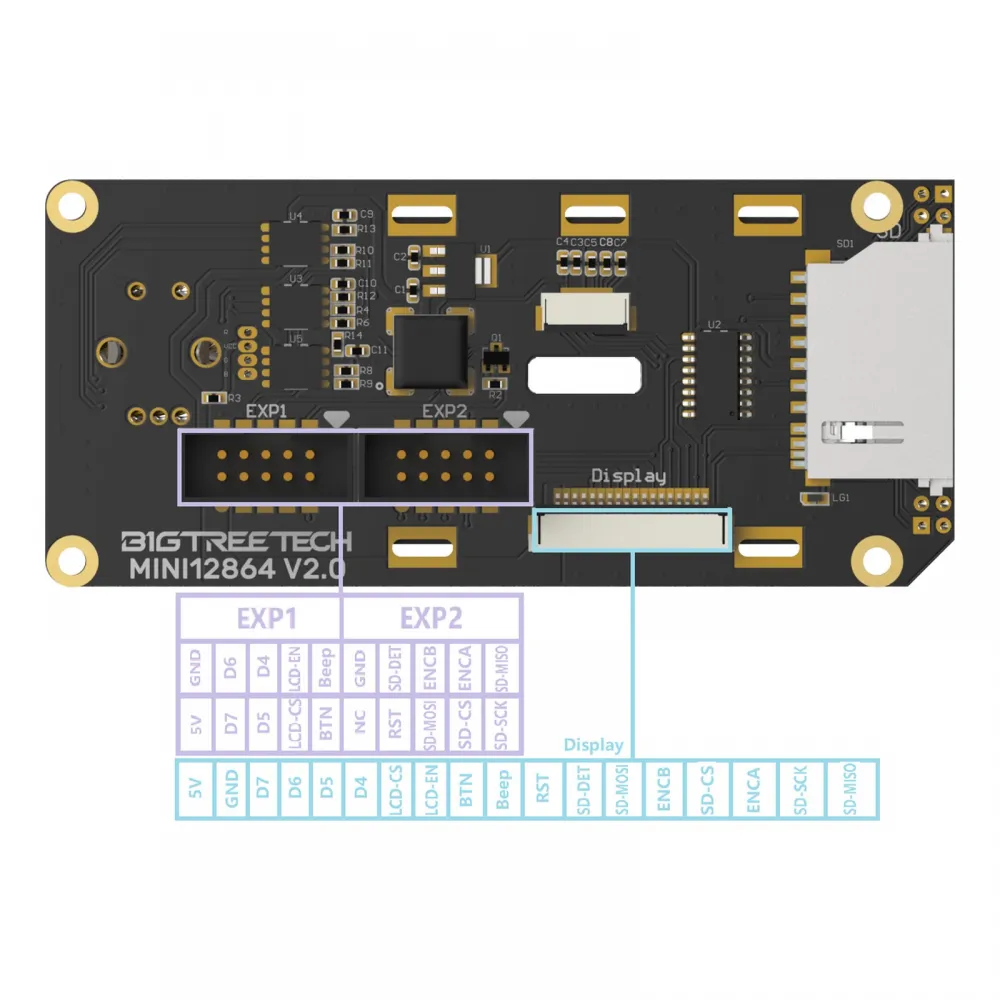
EXP1 carries power, LCD signals, the encoder push-button and beeper. EXP2 carries the encoder and SPI signals used by the SD card. The 18-pin FPC combines power, LCD, encoder, beeper, reset and SD signals. Read the diagram in the physical orientation shown; it must not be turned into a universal numbering rule for another controller.
| Interface | Documented signals | Purpose |
|---|---|---|
| EXP1 | 5 V, GND, D4-D7, LCD-CS, LCD-EN, BTN and Beep | LCD, click, lighting and beeper |
| EXP2 | GND, NC, RST, ENCA, ENCB, SD-DET, SD-MISO, SD-MOSI, SD-CS and SD-SCK | Encoder and SD card |
| FPC Display | 18 contacts carrying power, LCD, encoder, beeper, reset and SD | Direct connection to specifically prepared boards |
Controller-board and printer compatibility
BIGTREETECH documents this V2.0 connected to an SKR 3 through EXP1 and EXP2, and to an Octopus MAX EZ V1.0 through FPC. The BIGTREETECH Octopus V1.1 32-bit controller for Voron provides EXP1/EXP2 and can use a Mini12864 when its revision, wiring and firmware are configured specifically for it.
It is a common choice for Voron 2.4 and Voron Trident builds, but compatibility does not belong to the printer name alone: it depends on the installed controller, printed skirt or enclosure, cables, pinout and configuration. The same checks apply to custom machines using SKR, RAMPS or other RepRap boards.
It is not a direct replacement for every 12864 display or for the original Creality Ender-3, Ender-3 Pro or Ender-3 V2 screen. Such conversions may require an adapter, custom wiring, enclosure and recompiled firmware.
Current Marlin configuration
Current Marlin 2.1.x versions use the shared BTT_MINI_12864 definition for V1.0 and V2.0. Enable the following in Configuration.h:
#define BTT_MINI_12864
#define NEOPIXEL_LED
The older BIGTREETECH manual shows BTT_MINI_12864_V1; that name belongs to earlier Marlin versions and should not be copied without checking the installed source. The controller selected by MOTHERBOARD must supply the correct EXP1/EXP2 pins. Do not invent a NEOPIXEL_PIN when it is already provided by the board pin definition.
If the LCD lights up but remains blank after a firmware update, BIGTREETECH suggests loading defaults with M502 and saving them with M500 to restore the expected contrast. M502 resets every EEPROM setting, not only contrast: first record steps, PID values, offsets, mesh and any calibration that must be retained.
Klipper configuration
The BIGTREETECH V2.0 manual and Klipper's reference configuration use the uc1701 display type. This block only works when the controller's [board_pins] section defines the EXP1_n and EXP2_n aliases correctly:
[display]
lcd_type: uc1701
cs_pin: EXP1_3
a0_pin: EXP1_4
rst_pin: EXP1_5
contrast: 63
encoder_pins: ^EXP2_5, ^EXP2_3
click_pin: ^!EXP1_2

# Select only the alternative required by your board:
# spi_bus: spi
# spi_software_miso_pin: EXP2_1
# spi_software_mosi_pin: EXP2_6
# spi_software_sclk_pin: EXP2_2

[output_pin beeper]
pin: EXP1_1

[neopixel btt_mini12864]
pin: EXP1_6
chain_count: 3
color_order: RGB
initial_RED: 0.4
initial_GREEN: 0.4
initial_BLUE: 0.4
Do not copy aliases as though they were physical MCU pin names. Start from the example file for the exact controller and verify the GPIO mapped to every EXP signal. Some boards require hardware SPI and others use the shown software SPI pins; do not enable both alternatives at once. If the encoder direction is reversed, swap the order of its two entries in encoder_pins instead of changing the wiring.
RepRapFirmware use
BIGTREETECH does not provide a dedicated RepRapFirmware configuration for this display. Some Duet boards support ST7567/UC1701-family graphic displays, but support differs between the Duet 2 Maestro, Duet 3 Mini 5+ and other controllers and may require a purpose-built wiring loom.
EXP1/EXP2 alone are therefore insufficient proof of compatibility. Confirm the supported LCD controller, supply, signal map, encoder and RGB support, and the appropriate M918 command in the documentation for the exact board and RepRapFirmware version. The display SD reader may remain unavailable even when the LCD and encoder work.
Installation and troubleshooting
- Disconnect both the power supply and USB before handling EXP1, EXP2 or FPC.
- Check the MINI12864 V2.0 silkscreen and the schematic for the exact controller revision.
- Verify pin 1, GND, 5 V and cable continuity. EXP1 must match EXP1 and EXP2 must match EXP2 according to the actual pinout.
- Do not connect EXP1/EXP2 and FPC simultaneously unless the controller documentation explicitly requires it.
- Configure firmware for the display and controller before the first test.
- Test the image, encoder, click, reset, beeper, RGB and SD reader separately.
- If it remains blank, resets when the encoder turns, becomes hot or only partly works, switch off immediately and check orientation, pinout, SPI and configuration.
Differences from BIGTREETECH MINI12864 V1.0
V1.0 and V2.0 retain nominal overall dimensions of 104.99 × 47 mm, but they are not the same board. V2.0 adds the 18-pin FPC interface and changes the component and connector layout. The matching outline may allow some mounting designs to be reused, but depth, SD access, encoder position and internal clearances must still be checked.
For an alternative from another manufacturer with its own documentation, see the MKS MINI12864 V3.0 RGB display with microSD. Do not interchange them by copying the same firmware or wiring; compare controller board, pinout and revision.
Contents
- 1 × BIGTREETECH MINI12864 V2.0 display.
- 2 × IDC ribbon connection cables.
If the display must be placed farther from the electronics, the pack of two 1 m, 10-pin IDC ribbon cables for RepRap LCD EXP1/EXP2 is a conditional alternative. Check continuity, orientation, interference and stability at that length before replacing the original cables.
```