

- Stock: 26
- Model: Mini-12864-LCD-Fysetc

Model:

2004 LCD

12864 LCD

Mini 12864 LCD - Fysetc

Mini 12864 LCD - BTT

Mini 12864 LCD - MKS
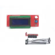
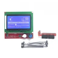
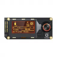
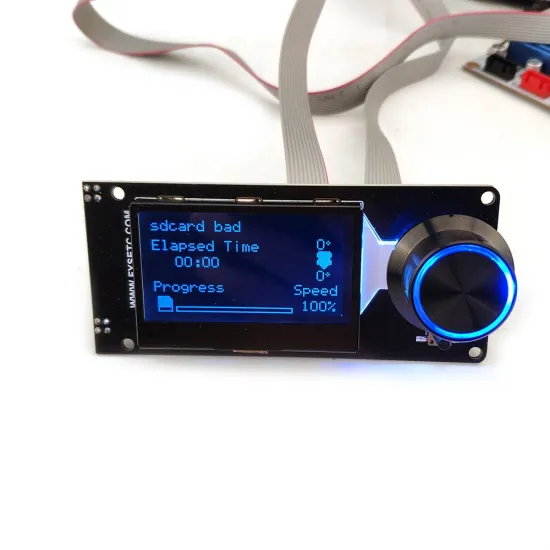
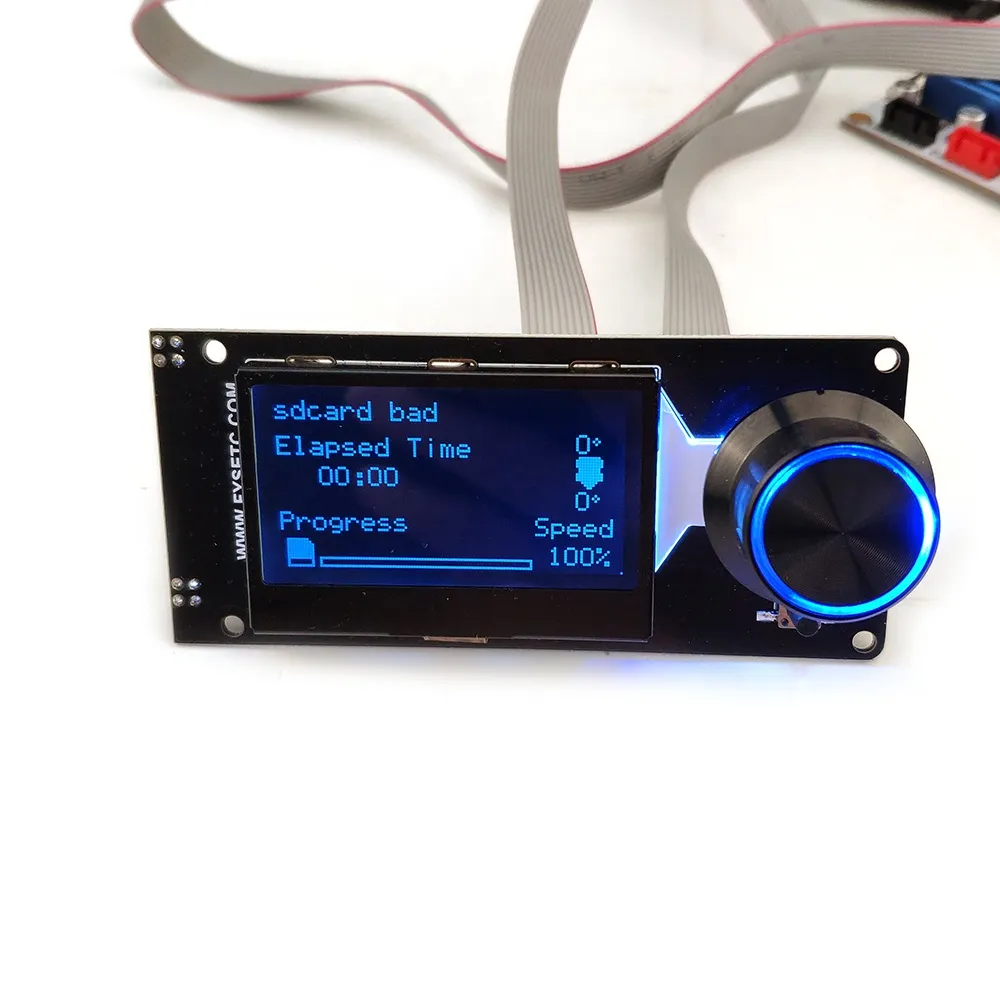
The FYSETC Mini 12864 V2.1 is a compact 128 × 64 graphic display for controlling compatible 3D printers, CNC machines and electronic projects through a rotary encoder. It integrates a microSD reader, clickable encoder, reset button, beeper and addressable RGB backlight.
Its approximately 2.4-inch format is particularly useful when a complete local interface is required without fitting a larger screen. Two IDC ribbon cables connect the panel through EXP1 and EXP2, but matching connectors alone do not guarantee compatibility: power, pinout, orientation and firmware configuration must all match.
Main features
- 128 × 64 graphic LCD: displays menus, temperatures, position, progress and firmware-defined machine status.
- Clickable rotary encoder: scrolls through menus, changes values and confirms selections.
- Addressable RGB backlight: three WS2811-controlled RGB groups, one for the display and two around the encoder.
- MicroSD reader: operation depends on the controller, SPI wiring and firmware configuration.
- EXP1 and EXP2: two 10-pin IDC headers for boards with a compatible electrical assignment.
- Reset/Kill and beeper: integrated configurable push-button and audible indicator.
- Configurable contrast: adjustable from supported firmware.
Technical specifications
| Feature | Value |
|---|---|
| Manufacturer and revision | FYSETC Mini 12864 V2.1 |
| Type | Monochrome graphic LCD with RGB backlight |
| Resolution | 128 × 64 pixels |
| Commercial size | 2.4 inches |
| Communication | SPI through EXP1/EXP2 |
| Firmware controller type | ST7567/UC1701 family |
| Power | 5 V from the display interface; internal 3.3 V regulation |
| Lighting | 3 addressable WS2811 RGB groups, RGB order in the official Klipper configuration |
| Controls | Clickable encoder, reset/kill and beeper |
| Storage | MicroSD slot with card detection |
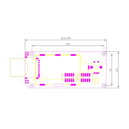
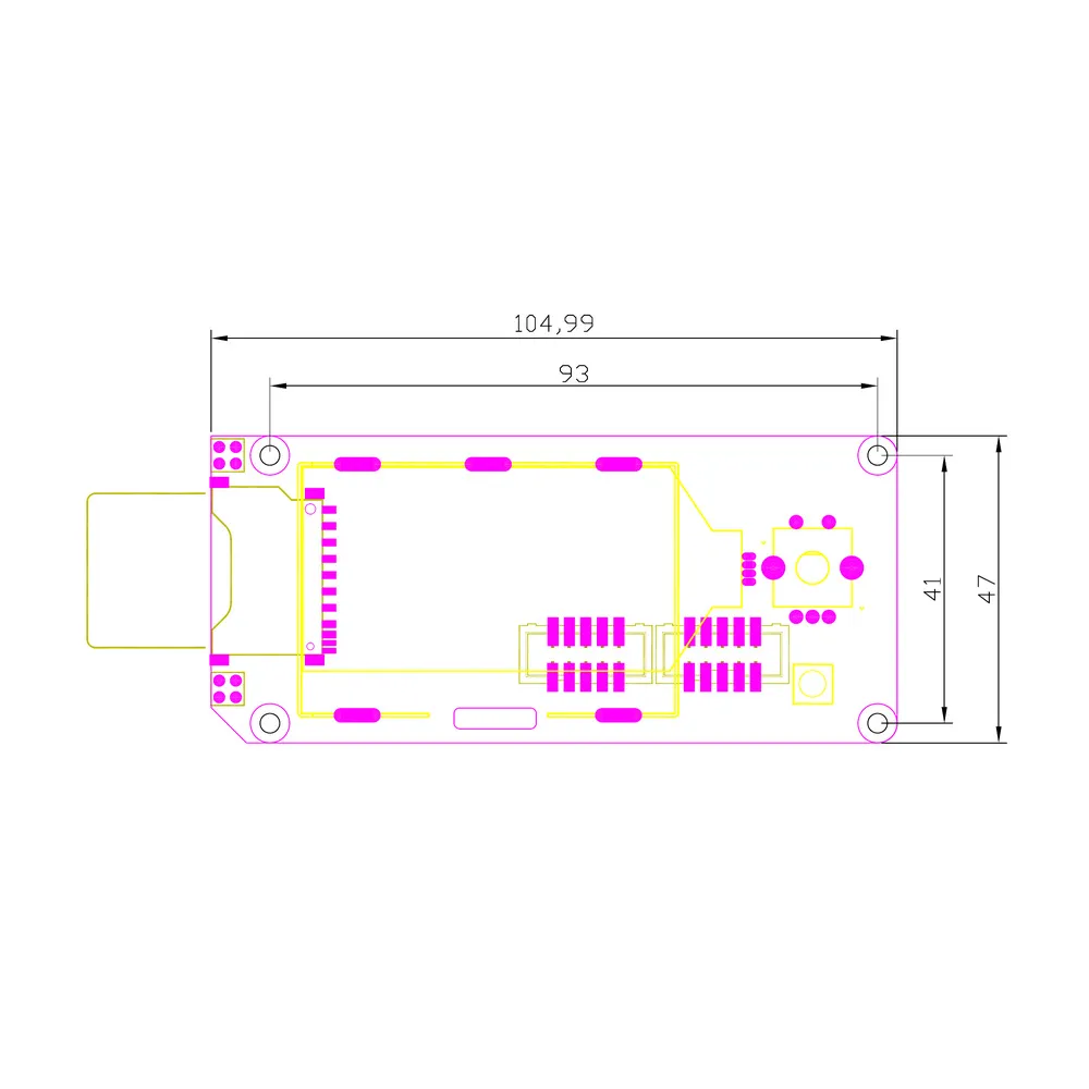
| Overall dimensions | 104.99 × 47 mm |
| Mounting centres | 93 × 41 mm |
| Documented firmware | Marlin, Klipper and selected RepRapFirmware boards |
EXP1, EXP2 and signals
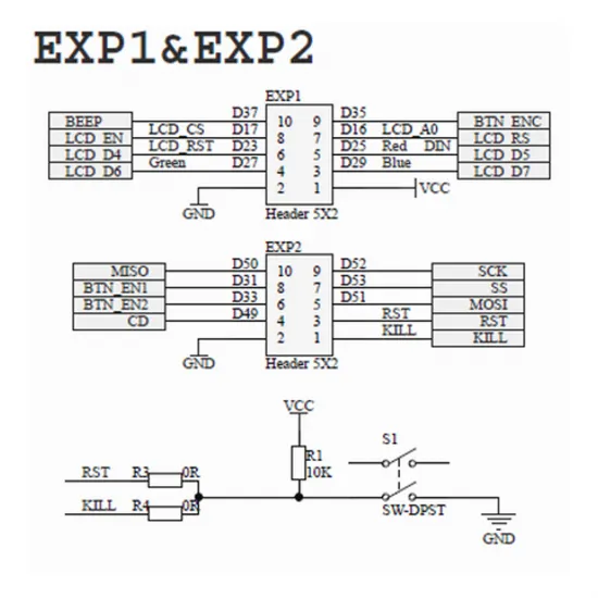
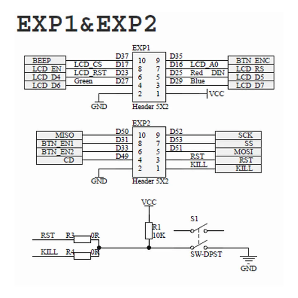
EXP1 groups power, LCD control signals, encoder click, beeper and the RGB lighting data input. EXP2 carries encoder signals, reset/kill, card detection and the SPI bus used by the microSD slot. The official schematic also shows the internal 3.3 V adaptation for the card and LCD signals.
| Interface | Main signals | Purpose |
|---|---|---|
| EXP1 | VCC, GND, BEEP, BTN_ENC, LCD_CS, LCD_A0, LCD_RST and RGB DIN | Power, LCD, click, beeper and lighting |
| EXP2 | MISO, MOSI, SCK, SS, BTN_EN1, BTN_EN2, CD and RST/KILL | Encoder, microSD card and reset/kill function |
Pin numbering may be shown from different perspectives in the display schematic and firmware aliases. Use the physical orientation in the official image together with the controller-board schematic; do not turn connector key position into a universal rule.
Important RST and KILL warning
FYSETC uses the R3 and R4 positions to adapt the display push-button to either RST or KILL. The manufacturer warns that some boards, including certain FYSETC S6 and Spider revisions, replace KILL with 5 V. If R4 connects that line to the button, pressing it could short 5 V to GND.
Controller-board compatibility
FYSETC defines EXP1 and EXP2 around the interface family used by RAMPS and other RepRap electronics. It can be integrated with the RAMPS 1.4 controller for Arduino Mega 2560 when the correct LCD adapter is available, signals match and firmware is configured for this revision.
It can also be used with modern controllers that document Mini12864 support, such as the BIGTREETECH Octopus V1.1 controller for Voron or the FYSETC Spider V3 controller, but a direct connection must not be assumed. IDC housing orientation may differ between manufacturers, while Spider combinations require particular attention to RST/KILL and schematic revision.
Two physically matching connectors are not proof of compatibility. Before purchasing or installation, verify:
- the exact display and controller revisions;
- pin 1, GND and 5 V on both connectors;
- cable orientation and continuity;
- availability of the SPI bus and encoder signals;
- firmware support for the FYSETC Mini 12864 V2.1 definition;
- possible conflicts with the controller's onboard SD card.
Voron compatibility
Official Voron documentation covers Mini12864 displays on Voron V1, Voron Trident, Voron 2.4 and Voron Switchwire. Compatibility is conditional on the installed controller, cables, printed mount or skirt and matching Klipper configuration.
On a dual-MCU Voron 2.4, the display must be configured on the microcontroller to which it is physically connected. The Voron guide also contains revision-specific instructions for certain FYSETC Spider boards and display/controller combinations from different manufacturers. These modifications must not be transferred automatically to a Spider V3 or another revision without checking its schematic.
Marlin 2.1.x configuration
Marlin includes a dedicated definition for this revision. Enable the following in Configuration.h:
#define FYSETC_MINI_12864_2_1Marlin's NeoPixel feature is also used to control the backlight:
#define NEOPIXEL_LEDV2.1 contains three RGB devices in one chain, but NEOPIXEL_TYPE, NEOPIXEL_PIXELS and the data pin must be reviewed against the Marlin version and controller pin file. Do not define NEOPIXEL_PIN manually when the controller already provides it for this display.
Marlin must be built for the exact controller model and revision. If the display microSD slot is required, check the SD connection option and any conflict with the controller's onboard card. After flashing, test the image, encoder, click, beeper, RGB and microSD separately.
Klipper configuration
Klipper maintains a dedicated reference block for the FYSETC Mini 12864 V2.1. The EXP1_n and EXP2_n names only work when the controller's [board_pins] section defines them correctly:
[display]
lcd_type: uc1701
cs_pin: EXP1_3
a0_pin: EXP1_4
rst_pin: EXP1_5
contrast: 63
encoder_pins: ^EXP2_5, ^EXP2_3
click_pin: ^!EXP1_2

# Select only the alternative required by your controller:
# spi_bus: spi
# spi_software_miso_pin: EXP2_1
# spi_software_mosi_pin: EXP2_6
# spi_software_sclk_pin: EXP2_2

[output_pin beeper]
pin: EXP1_1

[neopixel fysetc_mini12864]
pin: EXP1_6
chain_count: 3
color_order: RGB
initial_RED: 0.4
initial_GREEN: 0.4
initial_BLUE: 0.4
Do not copy EXP aliases as though they were physical GPIO names. Start from the example file for the exact controller and verify the pin map. Some boards use hardware SPI and others use software SPI; do not enable both alternatives simultaneously. If the encoder direction is reversed, swap its two entries in encoder_pins.
Klipper normally prints from host storage through [virtual_sdcard]. The panel's microSD slot is not automatically enabled when the LCD is configured and may remain unused.
RepRapFirmware use
Duet3D explicitly lists the FYSETC Mini12864 V2.1 among supported displays, but support depends on the board model and RepRapFirmware version.
| Controller | Documented compatibility | Main conditions |
|---|---|---|
| Duet 3 Mini 5+ | ST7567 supported | EXP1/EXP2 and suitable RRF version |
| Duet 2 Maestro | ST7567 supported | Modified wiring; RGB support conditional and untested in some versions |
| Duet 2 WiFi/Ethernet | ST7567 LCD from RRF 3.2 | Custom loom; NeoPixel from supported versions |
| Duet 3 6HC/6XD | No documented direct 12864 connection | Another interface or solution is required |
The display is enabled with M918 P1, while encoder and frequency parameters are selected for the specific board and installation. There is no single safe universal command line. NeoPixel lighting can be controlled with M150 when supported by the controller and RepRapFirmware version.
Safe installation and troubleshooting
- Fully disconnect both the power supply and USB.
- Confirm that the display is V2.1 and consult the schematic for the exact controller revision.
- Identify pin 1, GND and 5 V at both ends before fitting the cables.
- Check R3/R4 and the RST/KILL function before using the push-button.
- Configure firmware for the display and controller before the first test.
- Power up and test the LCD, encoder, click, beeper, RGB and microSD separately.
- If the controller resets when the encoder is pressed or turned, the LCD remains blank, becomes hot or only partly works, switch off immediately and check orientation, pinout and SPI.
Differences from other Mini12864 displays
This FYSETC V2.1 uses addressable RGB lighting. It must not be configured as a FYSETC V1.2 with fixed lighting or a V2.0 with discrete RGB control. Even where dimensions and signal families are shared with other Mini12864 displays, the commercial name does not replace revision verification.
For alternatives with their own manufacturer documentation, see the BIGTREETECH MINI12864 V2.0 RGB display with SD and the MKS MINI12864 V3.0 RGB display with microSD. Do not interchange them by copying the same wiring; compare controller, pinout, card access, mounting and firmware.
Contents
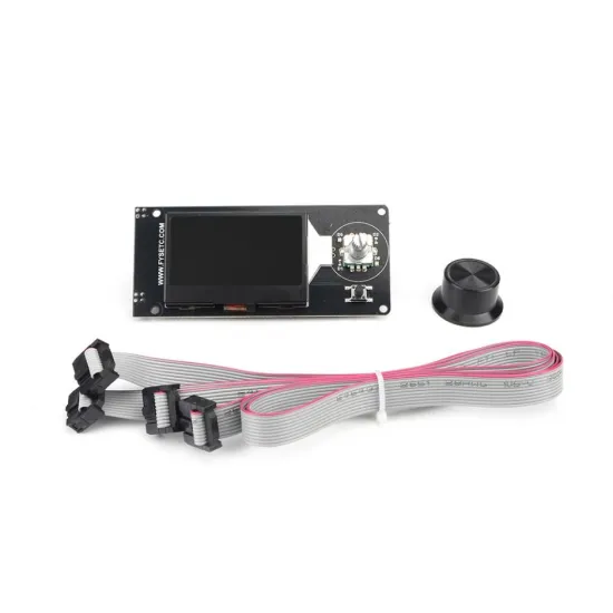
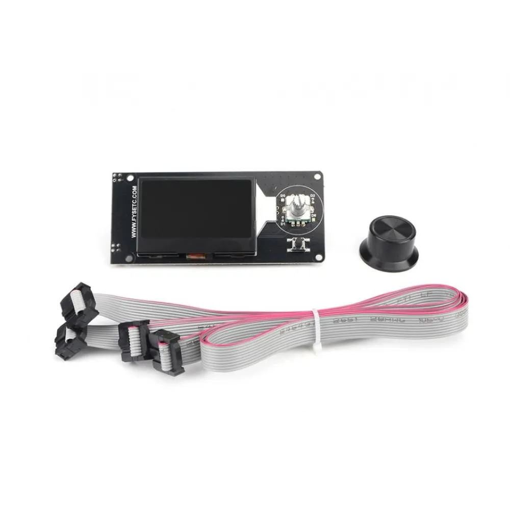
- 1 × FYSETC Mini 12864 V2.1 display.
- 1 × encoder knob.
- 2 × IDC ribbon connection cables.
If the display must be positioned farther from the controller, the pack of two 1 m, 10-pin IDC ribbon cables for RepRap LCD EXP1/EXP2 is a conditional alternative. Check continuity, orientation, interference and bus stability at that length before replacing the included cables.