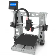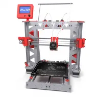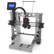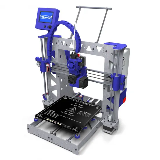
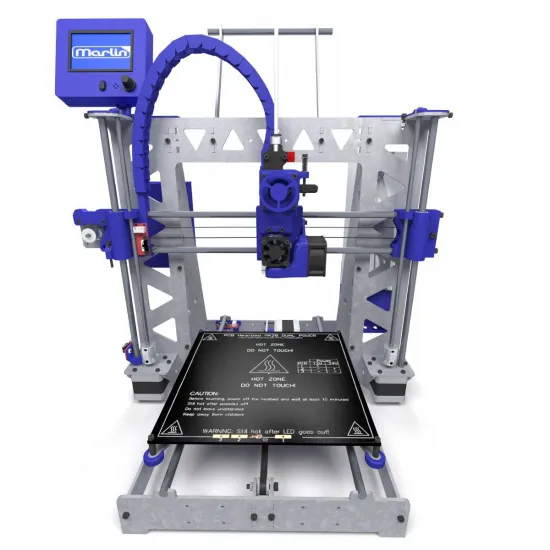
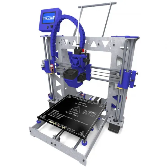
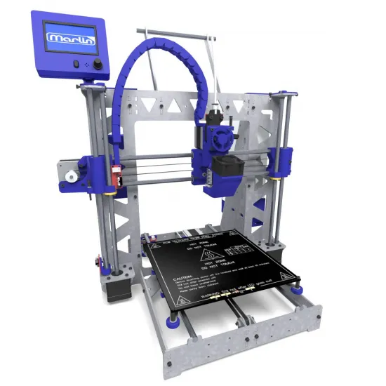
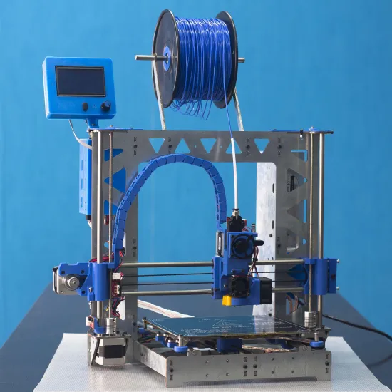
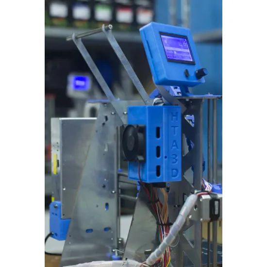
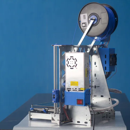
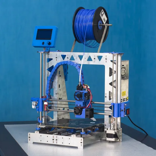
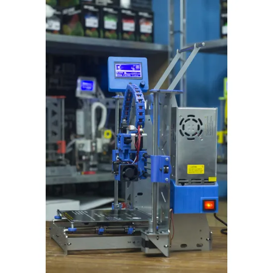
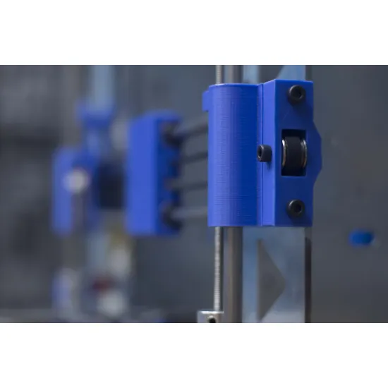
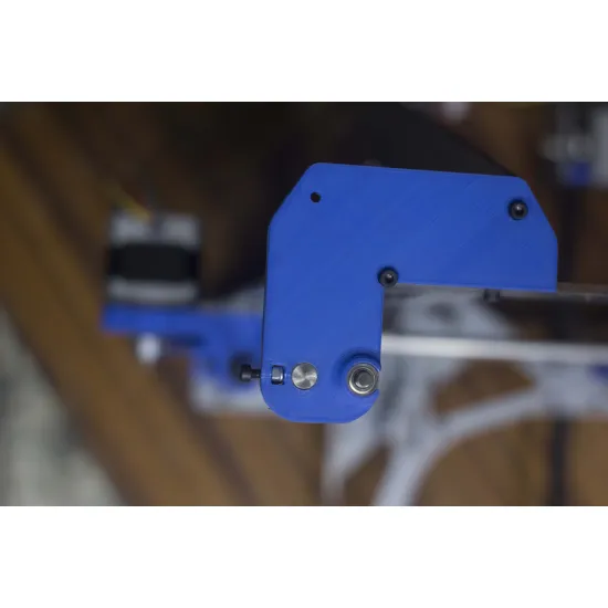
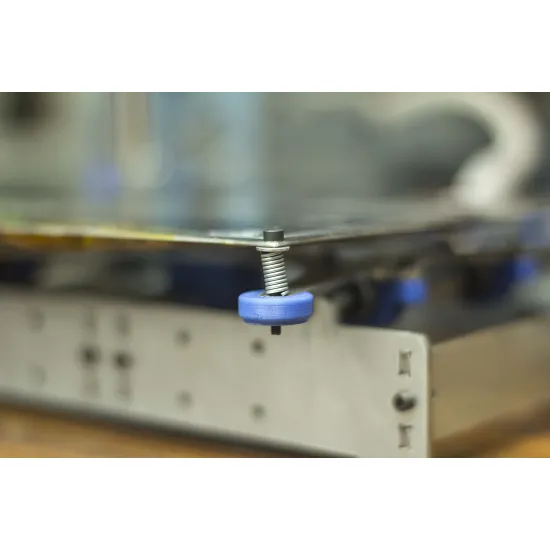
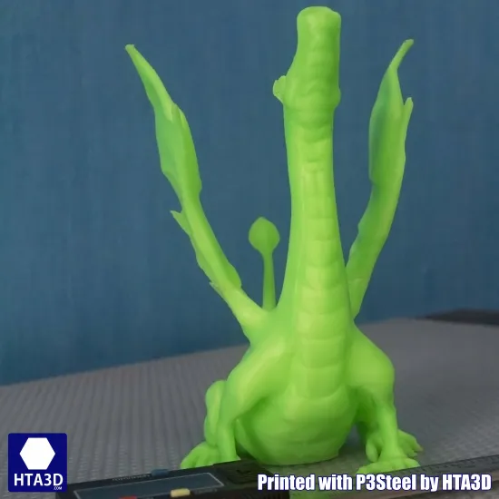
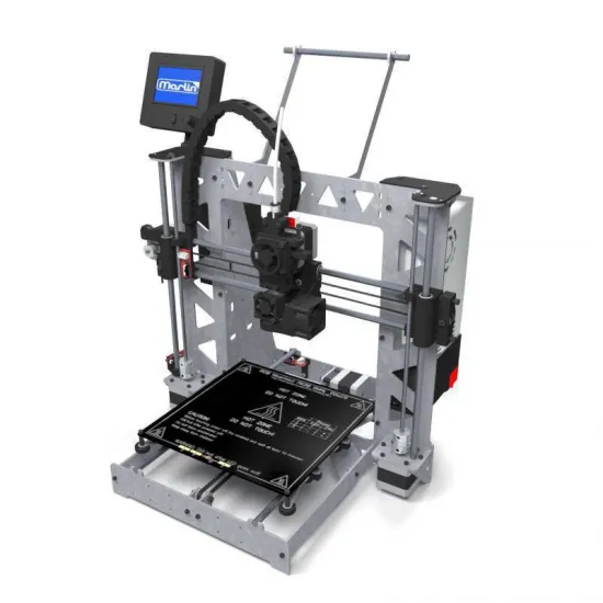
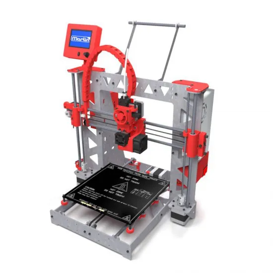
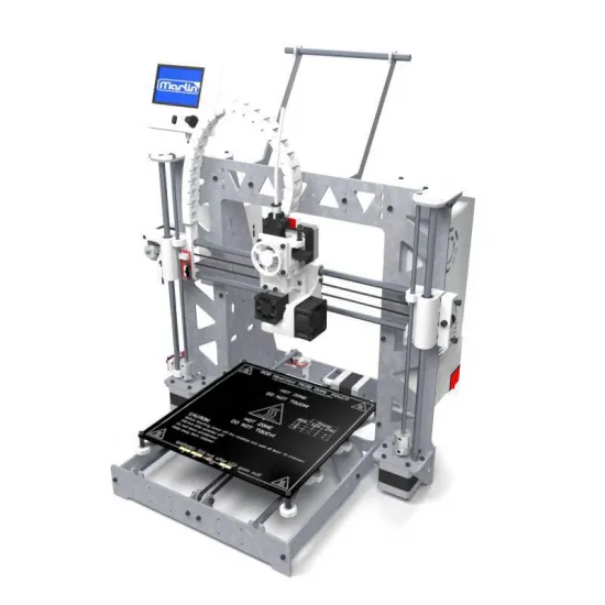


The HTA3D P3STEEL is a customisable DIY 3D printer kit with a steel frame, direct drive and an open architecture based on the RepRap/P3Steel family. Developed by HTA3D around 2015, it remains a functional, repairable machine and a particularly valuable way to learn how 3D-printer mechanics, electronics and firmware work.
Its single-extruder configuration has aged especially well: it avoids the complexity of aligning two fixed nozzles, keeps the filament path short and makes each system understandable to build, calibrate and modify. The kit is supplied unassembled, with firmware loaded and the drivers adjusted for the selected configuration.
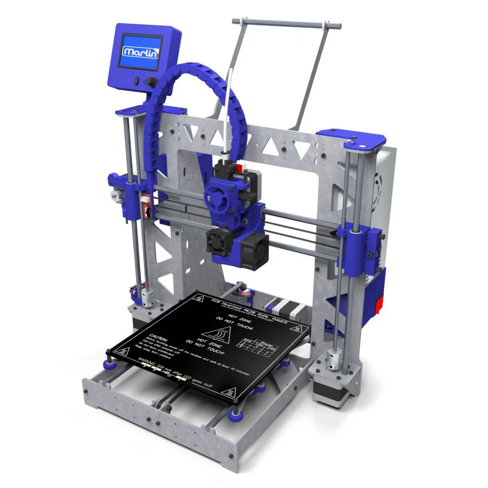
Main features
| Feature | Documented configuration |
|---|---|
| Build volume | 200 x 200 x 210 mm (X/Y/Z) |
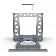
| Structure | 3 mm steel frame, galvanised or 304 stainless depending on option |
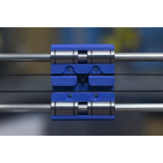
| Kinematics | Moving-bed Cartesian; GT2 on X/Y and M5 or T8x8 on Z |
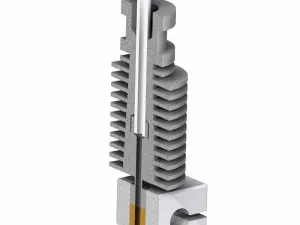
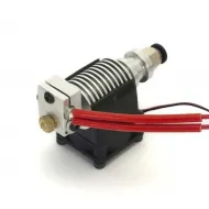
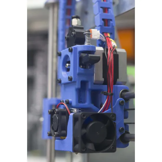
| Extrusion | Direct drive, 1.75 mm filament, NEMA 17, MK8 drive gear and V6 hotend |
| Electronics | Mega 2560-compatible board, RAMPS 1.4 or 1.5 and four drivers for X/Y/Z/E |
| Motors | Five: X, Y, two Z motors and extruder |
| Power | 12 V, 30/33 A power supply with switch and terminal guard |
| Control | 12864 graphic LCD with SD card reader |
| External dimensions | Approximately 47 x 38 x 60 cm with spool holder, plus clearance for bed travel |
| Weight | Approximately 11.5 kg in the basic configuration; varies with options |
Build volume and external dimensions are nominal. Actual usable travel may be affected by the assembled parts, build-surface clips, origin, firmware and assembly tolerances.
Why it still makes sense
- Genuine learning: assemble, wire, configure and calibrate every subsystem.
- Rigid frame: the steel structure provides a stable, durable base.
- Open architecture: Mega, RAMPS, Marlin, V6, NEMA 17, GT2 and 8 mm guides are familiar, repairable technologies.
- Direct drive: the short path aids filament control and can handle flexible materials well when the hotend and profile are suitable.
- Extensive documentation: HTA3D maintains illustrated instructions and an assembly video series.
- Customisation: choose the frame, Z drive, hotend, nozzle, bed and linear bearings.
It is not a current high-speed printer and does not include automatic levelling, networking, an enclosure or modern compensation systems as standard. Correctly assembled and tuned, it remains capable of producing useful, good-quality parts, especially with common materials and speeds appropriate to its architecture.
Available options
The combination selected when ordering takes precedence over photographs and documents from previous batches.
| Group | Current options | What to consider |
|---|---|---|
| Frame | Galvanised steel or 304 stainless steel | Finish, environmental resistance and cost differ |
| Z axis | Original M5; T8x8 with couplers; motors with integrated 310 mm T8x8 | Parts, couplers and steps per millimetre differ; do not exchange profiles |
| Hotend | All-metal V6; PTFE-lined V6; all-metal V6 with titanium and Brass heatbreak | Choose for the materials, temperature and retraction behaviour required |
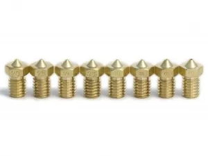
| Nozzle | 0.30, 0.35, 0.40, 0.50, 0.60 or 0.80 mm | 0.40 mm is a balanced starting point; larger sizes prioritise flow and wider lines |
| RAMPS | 1.4 or 1.5 | Identify the revision before repair, wiring changes or firmware updates |
| Heated bed | Red or black MK2B; aluminium MK3; 220 x 220 mm aluminium MK3 | Construction, thermal mass and build-surface arrangement vary |
| Linear motion | 12 LM8UU; 8 Igus DryLin plus 4 LM8UU on Z; 12 Igus DryLin | Check free movement and alignment before tightening the frame |
| Extras | Nine-nozzle set; borosilicate glass with four clips | Glass clips may slightly reduce usable area near the edges |
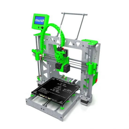
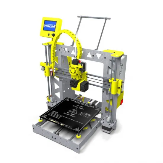
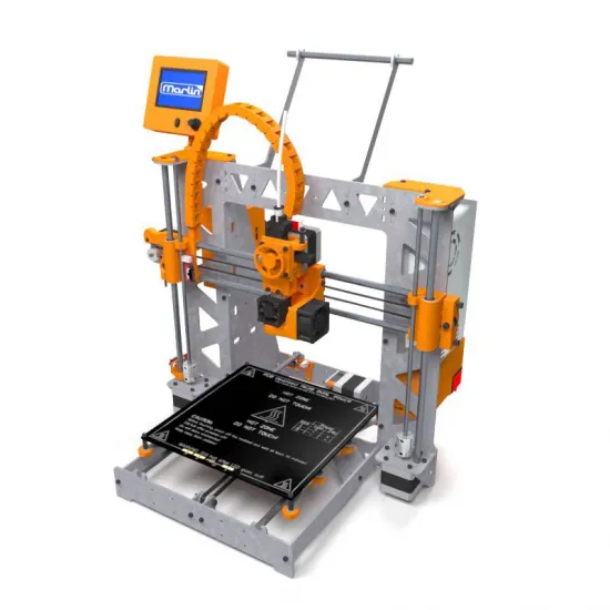
Printed parts can be selected in black, blue, red, white, green or yellow in the current selector. Colour availability may vary.
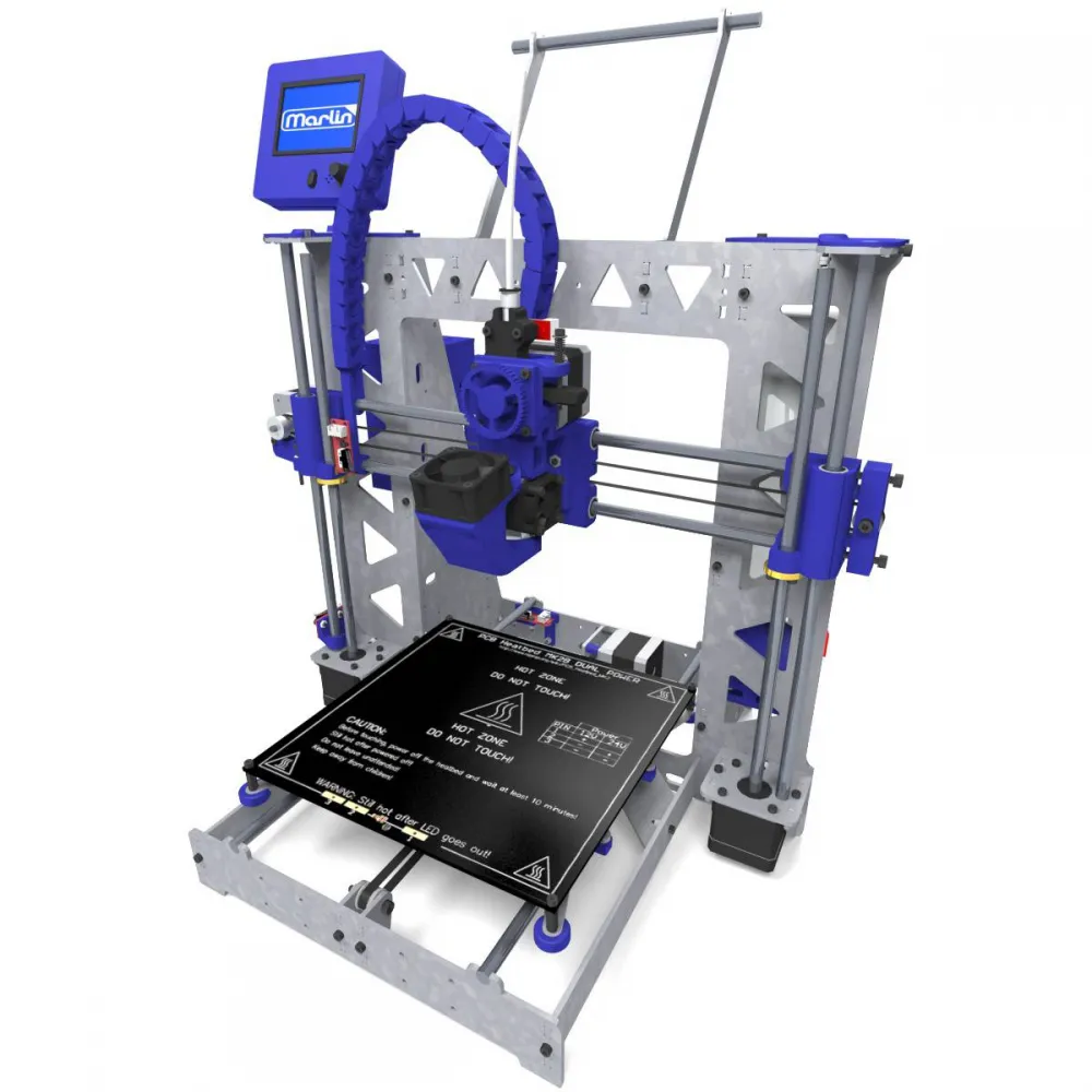
Kit contents
The kit groups the modules required to build the printer in the selected configuration. Specific components may change with options and stock evolution.
| Module | Main documented components |
|---|---|
| Structure | 3 mm main frame, side pieces, braces, Y-axis plates, lightweight carriage, brackets and upper spool holder |
| Motion | Six 8 mm smooth rods, selected Z transmission, twelve linear bearings/bushings, F624ZZ bearings, GT2 belt, 20-tooth pulleys and couplers where required |
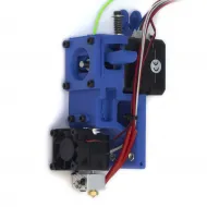
| Extrusion | HTA3D direct extruder, NEMA 17, MK8 gear, 623ZZ idler, V6 hotend, heater, sensor, nozzle and 3010/4020 fans |
| Electronics | Mega 2560-compatible board, selected RAMPS, four drivers, five motors, three endstops, 12864 LCD and wiring |
| Bed | Selected heated bed, thermistor, insulation, wiring, springs and adjustment parts |
| Power | 12 V PSU, switch, mains cable, terminals, protective earth and printed terminal guard |
| Assembly | Printed parts, cable chain, dedicated hardware, Kapton, heat-shrink, spiral wrap and cable ties |
For repairs or partial rebuilds, see the original HTA3D P3Steel direct extruder, HTA3D P3Steel hardware kit and galvanised P3Steel frame. Compatibility with modified community machines must be checked part by part.
Direct extruder, hotend and materials
The extruder motor moves with the X carriage. The MK8 gear pushes filament directly into the V6 through a short, constrained path. This simplifies retraction and can provide good control of flexible materials, although it adds moving mass compared with a modern Bowden system.
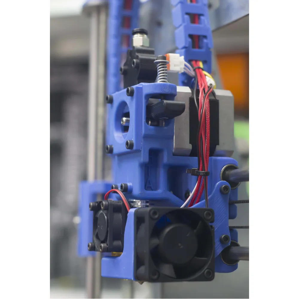
- PTFE-lined V6: offers a tightly guided path for common and flexible materials, but the tube approaches the hot zone. Respect the thermal limit of the installed PTFE.
- All-metal V6: removes PTFE from the melt zone and can support higher-temperature materials when the sensor, heater, wiring and rest of the system are also suitable.
- Titanium and Brass: a titanium heatbreak changes the thermal transition, while Brass components provide greater mass and conductivity than aluminium where included. Neither removes the need for cooling and calibration.
- PLA, PETG and common materials: natural applications with the correct profile and surface.
- ABS, ASA, nylon or PC: may require drying, a dedicated surface, higher temperatures and environmental control. The printer is open by design.
- Flexible filament: direct drive is beneficial, but hardness, guidance, idler pressure, nozzle and flow still determine performance.
There is no universal maximum temperature for every option. The safe limit is set by the lowest-rated component among the sensor, PTFE, heatbreak, heater, wiring, fan, block and firmware.
M5, coupled T8x8 or integrated T8x8
- Original M5: retains the historical solution and suits faithful builds or maintenance of an existing unit.
- T8x8 with couplers: uses separate lead screws joined to the motors, allowing either part to be replaced independently.
- Motor with integrated T8x8: removes the rotor-to-screw coupler but requires replacing the complete assembly if either element changes.
Each variant requires matching printed parts and configuration. Never copy M5 steps per millimetre to T8x8 or assume every lead screw sold as T8 has the same lead.
Assembly and commissioning
- Assemble and square the frame and Y axis before locking and tensioning the system.
- Install the selected Z variant and make both sides of the X axis level.
- Prepare the bed for its exact model and wire it for 12 V according to the matching diagram.
- Assemble the extruder, orient the MK8 gear and V6 block correctly, fit both fans and leave enough cable for full travel.
- Install the PSU, earth, switch and electronics with power disconnected.
- Power on to inspect the LCD and fans without requesting full movements.
- Test the hotend at a low temperature and the bed at about 40 °C, confirming that the correct sensor responds.
- Check each axis direction and endstop separately before full homing.
- Level both Z sides, manually level the four bed corners and test the full travel without collisions or cable tension.
- Calibrate extrusion, flow, PID, first layer and the material profile before increasing speed.
Marlin configuration
Marlin on Mega/RAMPS is the original and most natural configuration. Historical M5 and T8 downloads remain available, but firmware supplied with the kit and prepared for its options takes precedence over old files.
- Physically identify RAMPS 1.4 or 1.5 and the installed Z transmission.
- Check the board,
EXTRUDERS 1, volume, motor directions, endstops and limits before movement. - Do not copy Z steps between M5 and T8x8. Confirm the actual lead of the installed screws.
- Select temperature tables for the installed sensors. The documented bed uses a 100K Beta 3950 NTC and commonly corresponds to table 11 with a 4.7 kΩ pull-up; do not apply that setting to the hotend without identifying its sensor.
- Calibrate extruder steps with
M92and PID withM303. Review values usingM503and save withM500when EEPROM is enabled. M600requires advanced pause and related functions to be enabled in the build.
Converting to Klipper
Mega 2560 and RAMPS can act as a Klipper MCU, but conversion is not part of the supplied configuration. It requires a host, reflashing the board and creating a configuration for the actual revision and wiring.
Pins, directions, thermistors, rotation_distance, PID and limits are not universal. In the original architecture both Z motors usually share one driver; do not define independent channels without rewiring and verifying the electronics. Klipper can provide a current interface and tools, but it does not turn the mechanics into a high-speed printer.
Assembly documentation
HTA3D maintains an illustrated series covering the frame, M5 and T8 variants, bed, extruder, PSU, electronics, commissioning and flow calibration:
- Frame and Y axis.
- X/Z axes for M5 or X/Z axes for T8x8.
- Direct extruder.
- Electronics and wiring.
- Commissioning.
The tutorials cover several historical revisions. Follow the branch matching the supplied options and ask before changing power wiring or loading different firmware.
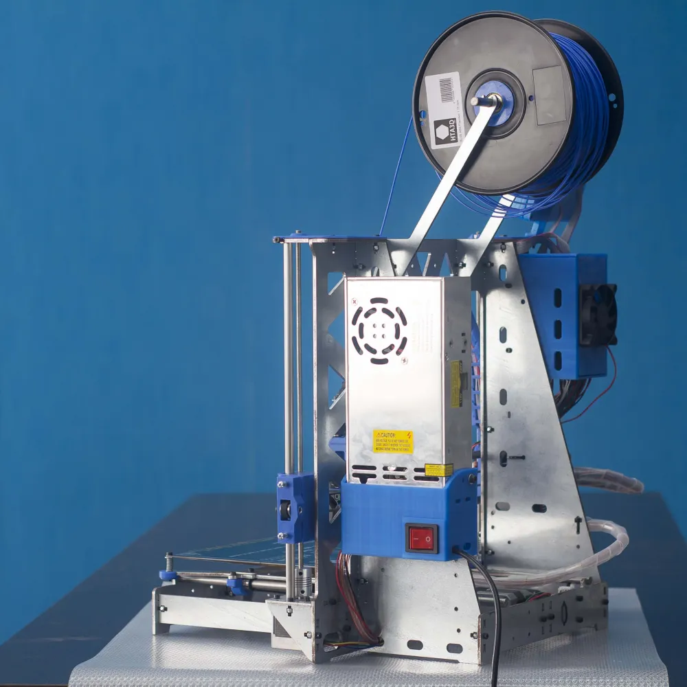
P3STEEL, P3STEEL DUAL or 3DSteel V2
| Model | Main strength | Choose it when... |
|---|---|---|
| P3STEEL | Simplicity, learning, direct drive and repairability | You want to build and understand an open, functional machine |
| P3STEEL DUAL | Two materials through two fixed nozzles | Dual extrusion justifies more complex calibration and maintenance |
| 3DSteel V2 | Later HTA3D platform, 24 V, 32-bit electronics and more current assembly | You prefer to invest somewhat more to reduce integration work and start from a modern base |
It is for you if
- You want to learn 3D printing from mechanics and wiring through to firmware.
- You value a steel structure, familiar components and a repairable machine.
- You prefer the simplicity and short path of a single direct extruder.
- You enjoy tuning and improving an open project.
- You need an original HTA3D P3Steel or want to maintain an existing unit.
It is not for you if
- You require a ready-to-use printer with automatic levelling, networking and automated profiles.
- Your priority is high-speed printing or a factory-enclosed build chamber.
- You do not want to assemble, verify wiring, level manually or learn calibration.
- You prefer a more modern platform for a moderate additional investment; in that case, consider the 3DSteel V2.
Assembly Tutorial
New step by step tutorials:
We have prepared a new updated tutorial serie, with further information about available options. Also printable, so you don't need a display to follow the instructions:
Assembly Tutorial (Spanish with english subtitles):
Important: We recommend reading the instructions in this tab completely, in addition to following the assembly from here since we have included additional information to the videos.
Updates:
- Thermistors have now dupont connector, no soldering required.
- Stepper motors include cable connector on base. In addition, we ship them with the wires in the correct order for Ramps 1.4. So you do not have to change the order.
- Marlin updated to 1.1.0 RC 7 version:
- Improved filament change system from the LCD or using command M600
- Bed leveling function optimized, get easily a perfect first layer.
- Small bugs fixed, now more information is displayed on the LCD.
Frequently asked questions:
- How all fans are connected to the printer?
Fans are connected as follows:- Layer fan: Connected to D9 as indicated in the video
- Hotend fan: connected directly to 12v, the connection can be done like on the video or connected to the output of 12v on Ramps 1.4
- Electronics Fan: connected directly to 12v, the connection can be done like on the video or connected to the output of 12v on Ramps 1.4
- The extruder motor does not move when I try to move it from the LCD.
Marlin has a protection to prevent accidental movement, so the extruder will not move with temperatures under 170°C. Try heating the hotend over this temperature and the extruder will move
Assembly drawings:
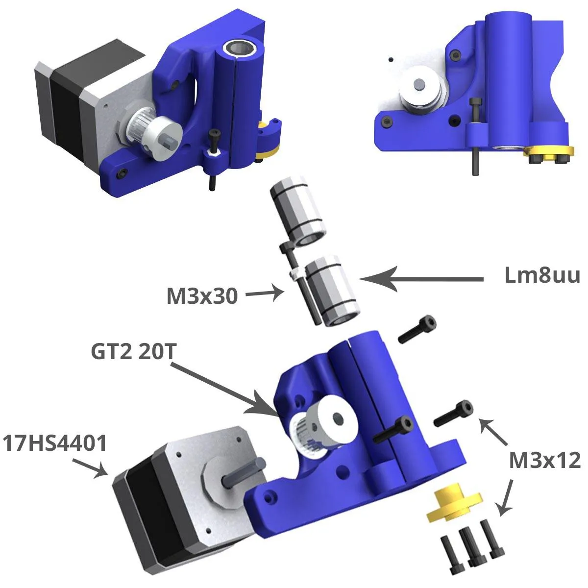
Xmotor, Leadscrews version:
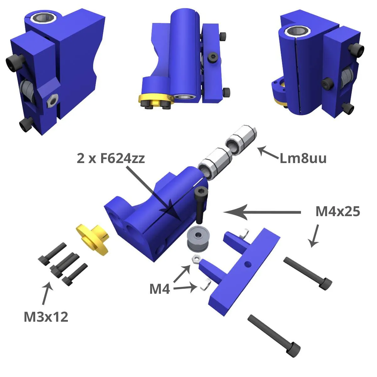
X idler, Leadscrews version:
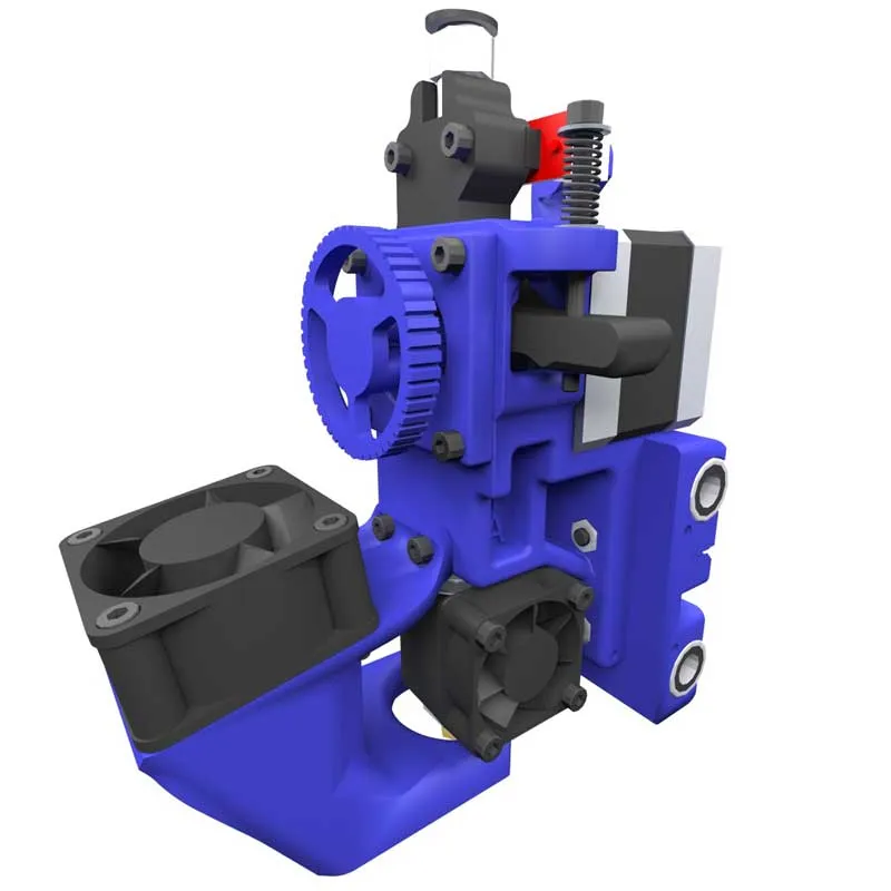
Extruder detail, Leadscrews version:
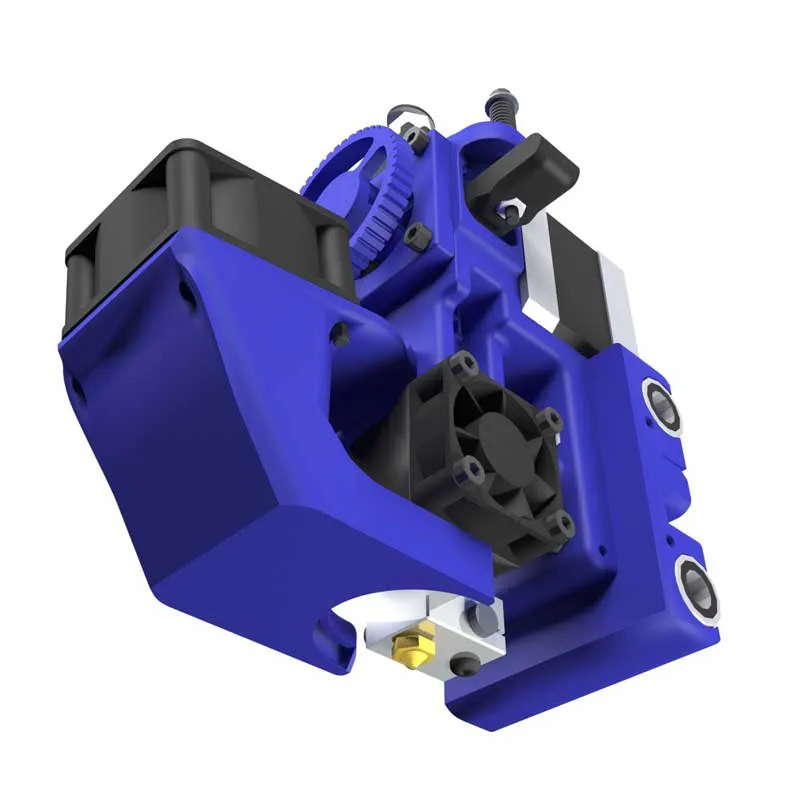
HotEnd detail, Leadscrews version:
Connection Diagram of RAMPS 1.4:
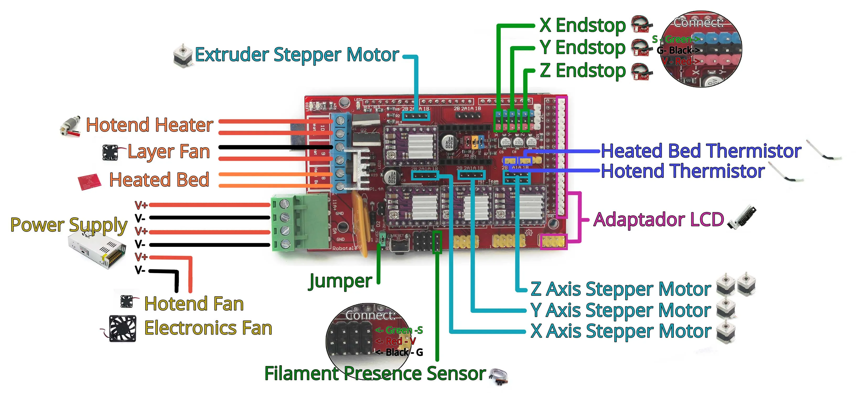
Order and Orientation of the Stepper Motor wires:
Keep the colour order of the wire; the RED wire goes DOWNWARDS when connecting to the RAMPS.
Additional considerations:
- Connect limit switches as indicated in the video or scheme, an incorrect connection can damage the Mega board.