

- Stock: Out of Stock
- Model: 3DTouch-Fysetc

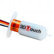
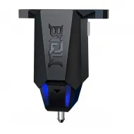
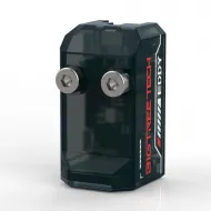
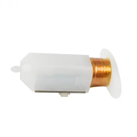
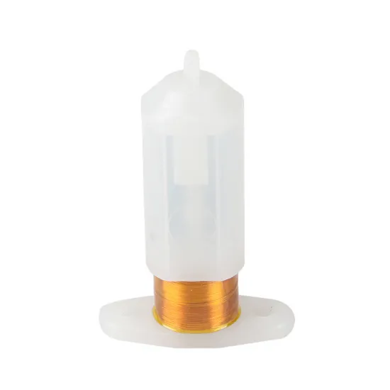
The Fysetc 3DTouch is a contact probe with a retractable pin, designed to measure the build surface so that the firmware can compensate for height variations during the first layer. Its operating principle is compatible with BLTouch-type probes, although this is a Fysetc product and not a genuine ANTCLABS BLTouch.
As detection is based on physical contact, the sensor can be used with glass, PEI, steel, aluminium and other stable build surfaces. It is not subject to the material and sensing-distance limitations of an inductive probe, but it requires a suitable mount, correct wiring and firmware configuration.
Main features
- Brand: Fysetc.
- Type: bed probe with deployable and retractable pin.
- Supply voltage: 5V.
- Declared current consumption: 15mA.
- Declared maximum peak current: 300mA.
- Weight: approximately 10g.
- Housing: semi-transparent.
- Short cable length: 150mm.
- Firmware support: Marlin, Klipper and RepRapFirmware, provided that the controller has the required connections and is configured correctly.
Wiring and signal order
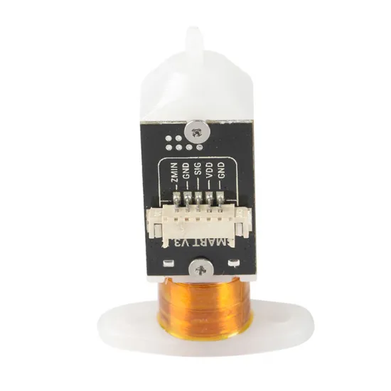
The probe PCB identifies its five connections as ZMIN, GND, SIG, VDD and GND. These functional markings should be used as the primary reference during installation.
- Brown: power ground.
- Red: 5V VDD supply.
- Yellow: servo or control signal.
- Black: sensor signal ground.
- White: Z-min or sensor output.
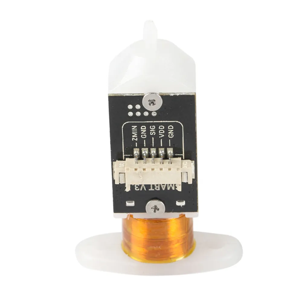
Important: always check the probe markings and the official pinout of your controller board. Connector orientation and pin order can vary between boards even when the plug physically fits. Incorrect wiring may damage both the probe and the controller.
This is a 5V device and must never be connected directly to a 12V or 24V output.
Mechanical installation
The mount must hold the probe firmly, vertically and without play. When retracted, the probe pin must remain above the nozzle tip; when deployed, it must reach the build surface before the nozzle.
Before starting any automatic movement:
- Manually check that the pin deploys and retracts without rubbing against the mount.
- Make sure the probe can reach every measuring point without moving the nozzle or sensor outside the bed.
- Configure the correct X and Y offsets for the actual probe position.
- Calibrate the Z offset after changing the nozzle, hotend, mount or probe.
- Perform the first test away from the bed and be ready to switch the printer off if the downward movement does not stop.
Marlin configuration
Marlin supports BLTouch and compatible probes through:
#define BLTOUCHThe levelling method, nozzle-to-probe offsets and actual input pin must also be configured. If the white signal wire is physically connected to the Z-min input, the relevant option may be:
#define Z_MIN_PROBE_USES_Z_MIN_ENDSTOP_PINThis option must not be enabled when the probe uses a different dedicated input. When the probe replaces the Z endstop, it is usually advisable to enable:
#define Z_SAFE_HOMINGThis moves the toolhead to a safe XY position before homing Z. The selected coordinates must place the probe—not only the nozzle—inside the build surface.
Before running a complete levelling cycle, test deployment and retraction and use M119 to confirm that the probe input changes state correctly. Do not change signal inversion or advanced BLTouch modes without first checking the controller documentation and the actual response of the probe.
Klipper configuration
Klipper requires a [bltouch] section containing the controller’s actual pin names:
[bltouch]
sensor_pin: ^INPUT_PIN
control_pin: CONTROL_PIN
x_offset: X_VALUE
y_offset: Y_VALUE
z_offset: INITIAL_VALUE
The ^ prefix enables the input pull-up and is required by many installations, but this must be confirmed for the controller board. If the probe is used for Z homing, the Z stepper section should include:
endstop_pin: probe:z_virtual_endstopA correctly positioned [safe_z_home] section with sufficient z_hop is also normally used.
Klipper recommends testing both signals before the first downward movement:
BLTOUCH_DEBUG COMMAND=pin_down
QUERY_PROBE
BLTOUCH_DEBUG COMMAND=pin_up
Probe height and repeatability can then be calibrated with PROBE_CALIBRATE and PROBE_ACCURACY. Some compatible probes may require additional parameters, but these should not be enabled by default. Only use them when the tests and the official Klipper documentation indicate that they are required.
RepRapFirmware configuration
RepRapFirmware provides a specific mode for BLTouch and similar probes:
M558 P9 C"INPUT_PIN" H5 F120 T6000The pin name, pull-up and any required inversion depend on the Duet model and board revision. The control output is normally assigned using M950, while G31 defines the measured X/Y offsets and Z trigger height.
Deployment and retraction are handled through deployprobe.g and retractprobe.g. A typical installation uses M280 commands in these files, but the servo index must match the output previously assigned with M950.
Before moving the nozzle towards the bed, test deployment and retraction with M401 and M402 at a safe height and confirm that the input detects contact.
Package contents
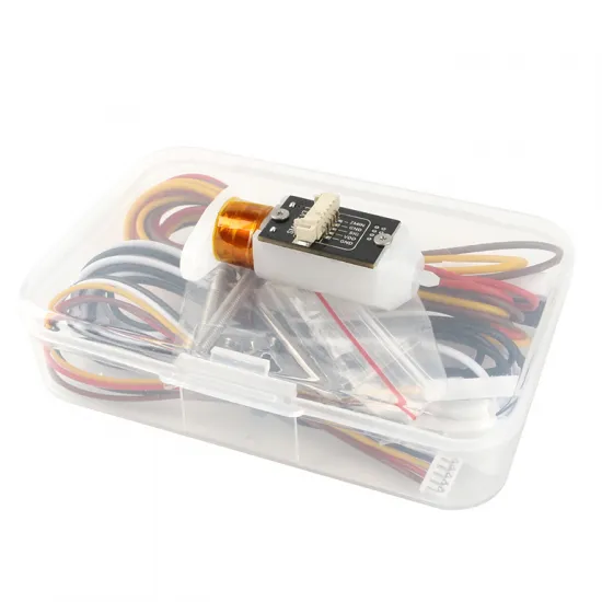
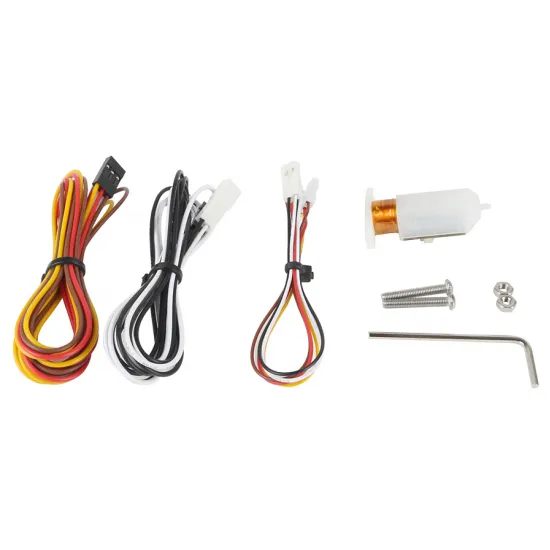
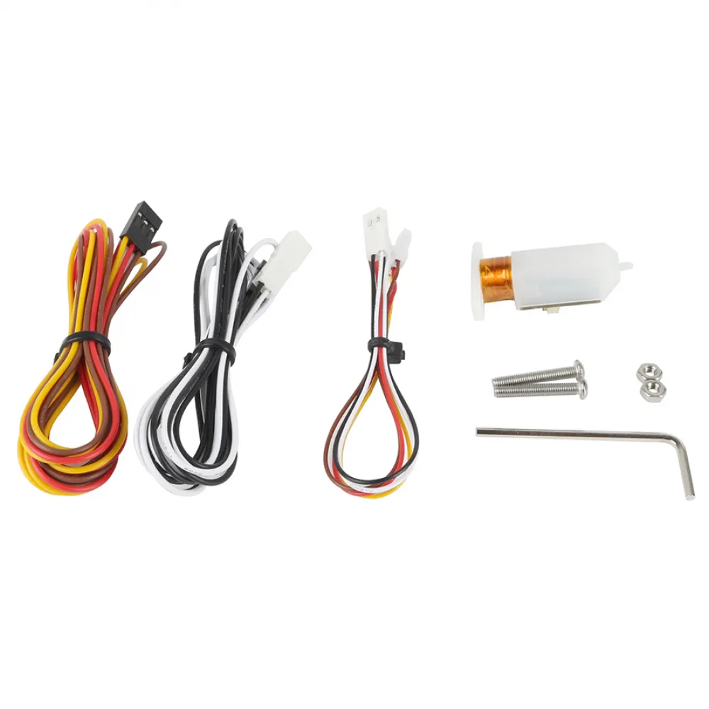
- Fysetc 3DTouch sensor.
- 150mm five-wire short lead.
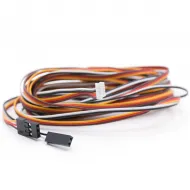
- Three-wire extension cable with DuPont connectors.
- Two-wire extension cable with DuPont connectors.
- Two mounting screws.
- Two nuts.
- Allen key.
Cable extension
If the supplied wiring is not long enough, the 2-metre extension cable for 3DTouch sensors can be used. Before applying power, make sure that every conductor matches both the probe PCB markings and the controller pinout.
What automatic bed levelling actually does
The probe cannot mechanically correct a loose, warped or incorrectly assembled bed. It provides measurements that allow the firmware to calculate a mesh and compensate for small height variations while printing. A stable mechanical assembly and accurate calibration are still essential for a reliable first layer.
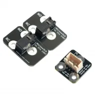
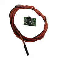
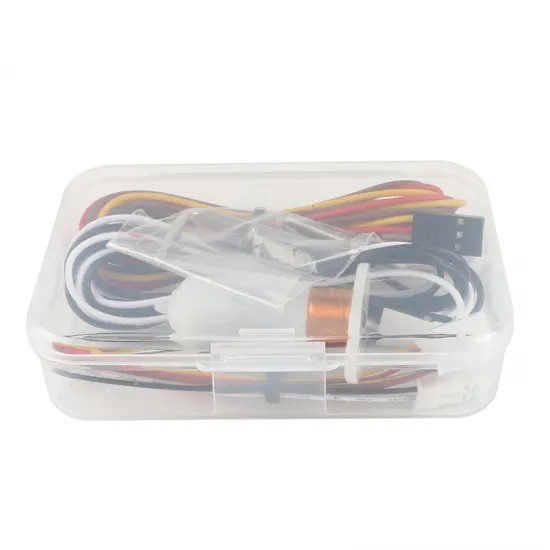
Contents: 1 Fysetc 3DTouch set with the wiring and accessories shown.