

- Stock: 999
- Model: PiezasImpresas-EjeX-3DSteel
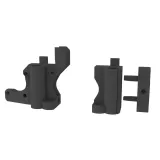
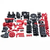
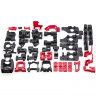
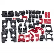
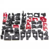
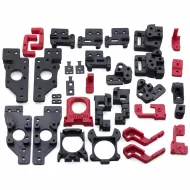
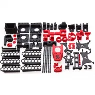
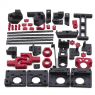
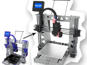
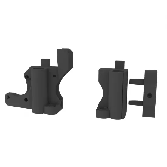
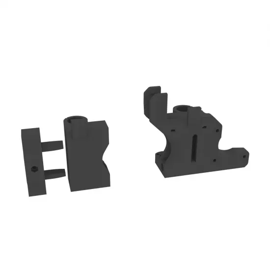
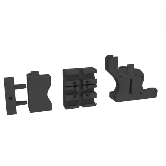
A set of black PETG printed parts for building or repairing the HTA3D 3DSteel X axis. The base set contains both X ends and the sliding belt tensioner; the X carriage and fasteners are available as separate options.
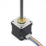
These parts work together with the rods, bearings, Z lead screws, motor and transmission used by the original design. They are not a universal set for every P3Steel or Prusa i3 Steel.
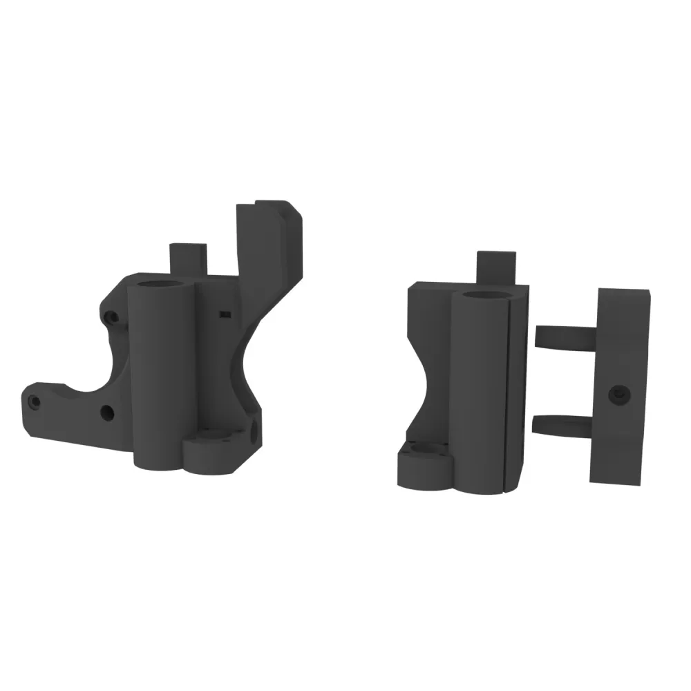
Base contents
- 1 motor-side X end.
- 1 belt-return and tensioner-side X end.
- 1 sliding X-axis tensioner.
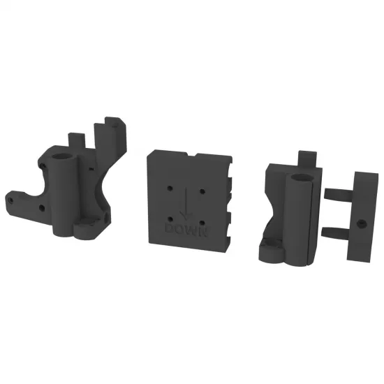
The renders illustrate the design geometry. Surface finish and minor marks inherent to FFF printing may vary between units without affecting their function.
Available options
X carriage
The square X carriage shown in some images is not included as standard. It is supplied only when its option is selected. The face marked DOWN identifies its lower orientation during assembly.
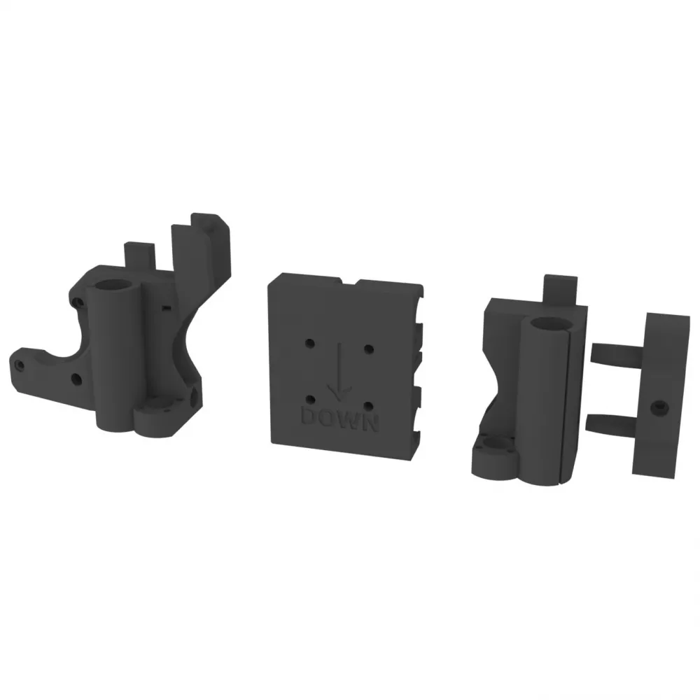
The option contains the printed carriage body. Bearings, belt, hotend, extruder, fans, wiring and other components are not included unless another option explicitly states otherwise.
Fastener kit
| Item | Quantity |
|---|---|
| M3 × 12 screw | 7 |
| M3 × 20 screw | 1 |
| M4 × 25 screw | 2 |
| M3 nut | 1 |
| M4 nut | 2 |
This option is specific to the X-axis subset. It is not equivalent to the complete 3DSteel V1/V2 fastener kit.
Compatibility
Intended compatibility is with the corresponding mechanical revision of the original HTA3D 3DSteel. The complete 3DSteel printed-parts set is available when more parts require replacement.
Both X ends also travel along the Z-axis rods and interface with its lead-screw and nut geometry. Before use, all of the following must match:
- diameter and spacing of both X rods;
- Z rods and LM8UU bearing seats;
- type and position of the Z lead screws and nuts;
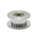
- X-motor mounting pattern and pulley height;
- tensioner bearing, axle and travel; the HTA3D design uses an F624ZZ-based return as a reference;
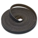
- belt type, width and running line;
- frame mounting points and available clearance.
Installation and alignment
- Switch the printer off and fully disconnect it. Support the X axis before removing the belt, motor or rods.
- Photograph the original orientation and compare the new parts with those removed, especially the bearing and Z-nut seats.
- Install bearings without impacts or pressure on their seals. Do not tighten the PETG until it deforms a bearing's outer shell.
- Insert both X rods to the same depth in the two ends and verify that they remain parallel.
- Fit the Z components without forcing the lead screws or applying side load to the bearings.
- Install the motor, pulley, return and tensioner. The belt must remain parallel to the rods and run in a single plane.
- When adding the X carriage, observe the
DOWNmark and check bearing, belt and wiring orientation. - Move the X carriage and both Z sides manually before tensioning. There must be no binding or height mismatch.
- Apply only enough tension to remove slack, then perform the first powered movements slowly and be ready to cut power.
Adjustment and maintenance
- Excessive tension may flex rods, load bearings, deform the tensioner and cause skipped steps.
- If the tensioner reaches the end of its travel, check belt length and anchor positions.
- After working on the X ends, level both sides and verify X-axis squareness before printing.
- Periodically inspect for cracks, layer separation, loose screws and wear in bearing seats.
- Replacing these parts does not require changing steps per millimetre when the original pulley, belt, microstepping and lead screws remain unchanged.
Not included
Motor, pulley, belt, LM8UU or F624ZZ bearings, rods, lead screws, Z nuts, hotend, extruder, electronics and wiring are not included. The X carriage and fasteners are supplied only when their respective options are selected.
Order preparation
This product is customised according to the selected options. The current listing states an approximate handling time of 24 to 72 hours before dispatch.