

How to Calibrate Stepper Motor Drivers
In this post we are going to explain how to calibrate the stepper motors drivers for our 3D printer.
We need:
- Power supply with power cable
- Arduino Mega + Ramps 1.4
- 1x Stepper Motor
- Small ceramic screwdriver
- Stepper motor drivers to calibrate
We can do it in two different ways: measuring the voltage or current intensity. We recommend doing it with current intensity, as it is safer and simpler.
We are going to calibrate the current intensity we want for each axis and for the extruder. The needed current intensity depends on each printer. In the case of our P3steel, we calibrate them as follows:
- X Axis: 0.3A
- Y Axis: 0.3A
- Z Axis: 0.6A
- Extruder: 0.4A
Thus each motor receives 0.3A, except the extruder, that received a bit more (0.4A).
Steps to follow:
We connect the LCD, the stepper motor in one axis and the stepper motor driver to calibrate in the same axis, carefully not to connect it the other way around.
We upload the firmware, if we haven't done it yet. We have two options:
We connect the thermistors to have a real reading.
We use the "Dummy" temperature tables for the thermistors, and we will have a programmed reading:
* 998 : Dummy Table that ALWAYS reads 25°C or the temperature defined below.
* 999 : Dummy Table that ALWAYS reads 100°C or the temperature defined below.
We connect the power supply in series to the 5A feeding of the Ramps 1.4 measuring direct current with the polimeter, following the scheme:
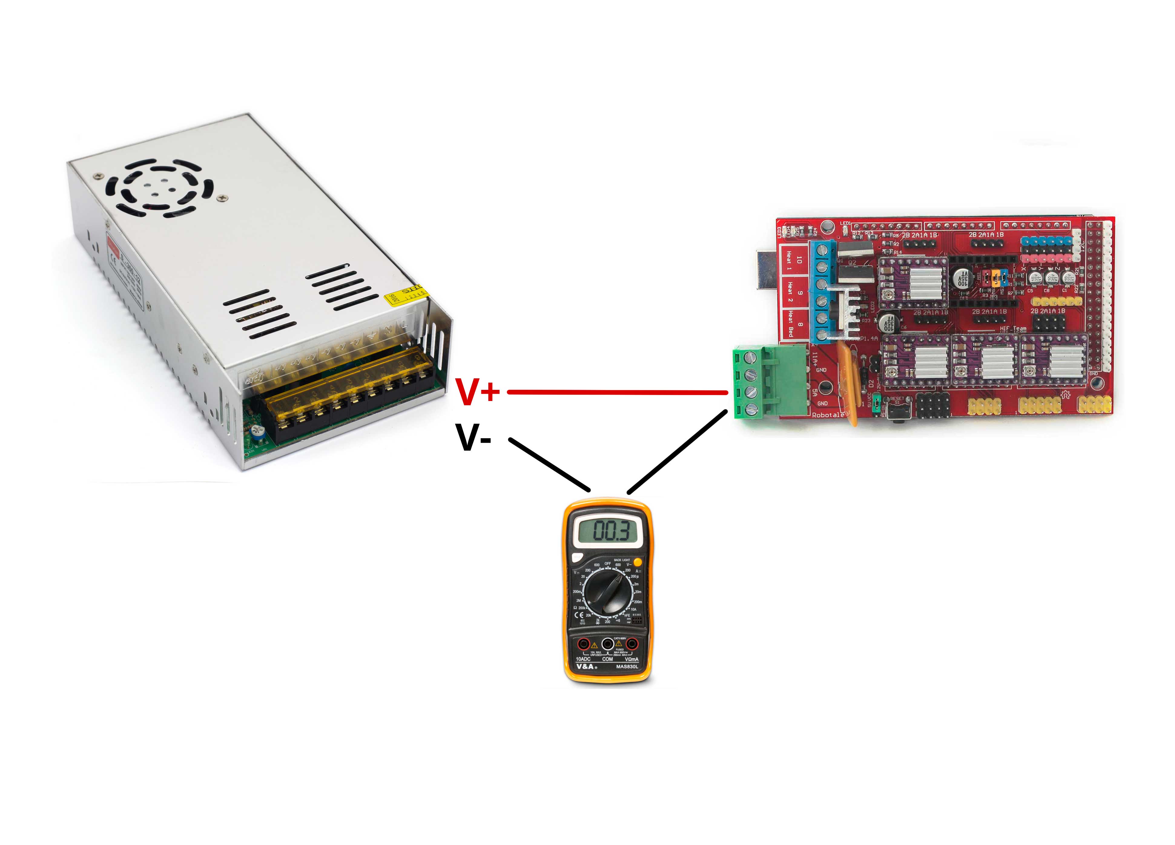
We turn on the power supply and we annotate the value that gives us the polimeter (0.08 A in this case).
We move the axis which we have connected the stepper motor and driver, and we annotate the given value. The current intensity that has the driver is the second value (0.65 A) minus the previous value (0.08 A), being 0.65 – 0.08 = 0.57 A in our video.
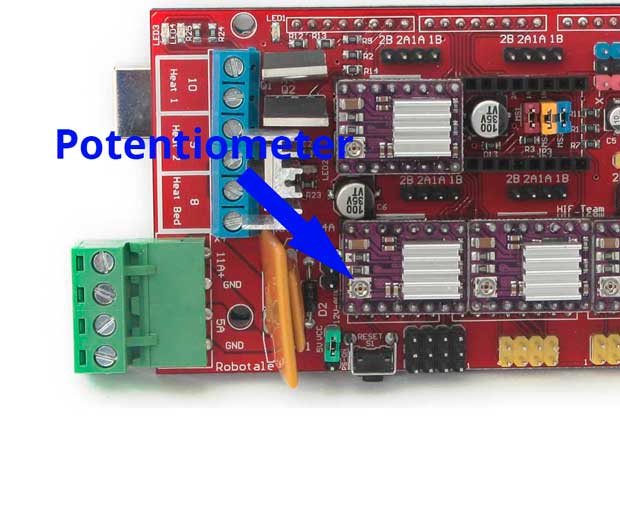
This driver is meant to be the X axis driver, so we have to turn the potentiometer until it gives 0.38 A, which is 0.3 A for the X axis + 0.08A for the electronics.
We have to do this step with every driver we are going to use. We can just change the driver without changing the position of the stepper motor, ordering from the LCD to move the same axis, knowing for which position we are calibrating it. Or changing the stepper motor depending on which driver we are going to calibrate. We have to have in mind that the extruder stepper motor will not move if we have activated the its protection and the temperature is below 170ºC.
Cautions:
- If we are not using a ceramic screwdriver, we mustn't touch the driver with the screwdriver while there is electrincial feeding. We must turn it off, turn the driver potentiometer, turn the electrincal feeding on and check the value it gives us. In the case we are using a ceramic screwdriver (as on the video) we can touch the driver, but ONLY if we are using a ceramic screwdriver
- We mustn't place the stepper motor drivers the other way around, as it can get damaged
- The extruder will not move when we order of the extruder temperature is below 170ºC if we have activated its protection
Related Products


")
 16u2")


1 Comment(s)
PRUSA i3...voy cambiar la Ramps 1.4 por la placa Ramps 1.6.\r\n\r\nQue pasos debo seguir?
La distribución de pines es equivalente, por lo que puedes simplemente reemplazar una por otra.
Leave a Comment