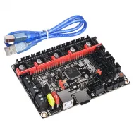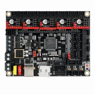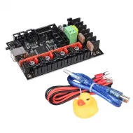


- Stock: 2
- Model: R4-Fysetc

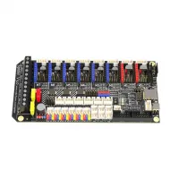
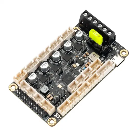
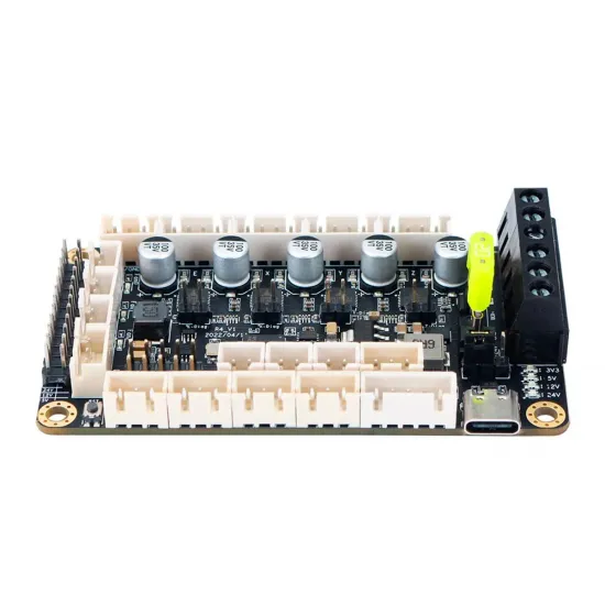
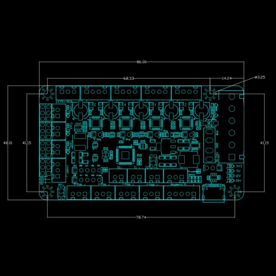
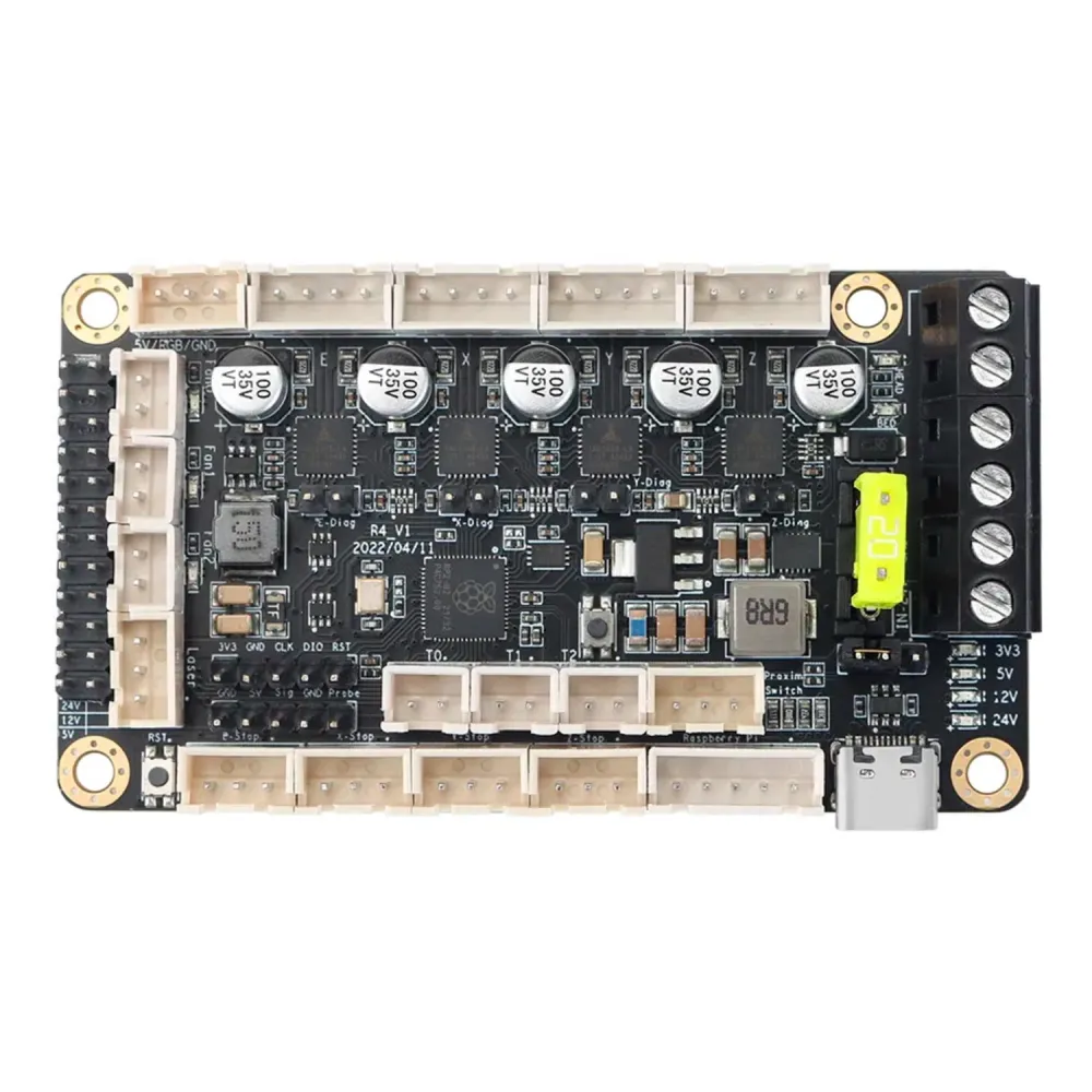
The FYSETC R4 is a compact 24 V controller board designed for four-motor Klipper 3D printers, with a particular focus on the Voron V0 family. It combines an RP2040 microcontroller, four UART-controlled TMC2209 drivers, bed and hotend outputs, three voltage-selectable fan outputs, three temperature inputs, and connections for endstops, a probe and addressable RGB.
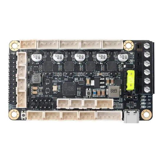
The supplied board is identified by the R4_V1 silkscreen. This revision and its pinout match FYSETC's official schematic, CAD and documentation for R4 V1.0.
Main features
- RP2040 microcontroller with dual-core Arm Cortex-M0+ CPU up to 133 MHz.
- 264 kB internal SRAM and 2 MB external flash identified in the schematic.
- Four integrated TMC2209 drivers for X, Y, Z and the extruder.
- UART control of all four drivers with separate addresses.
- USB-C connection and UF2 firmware updates.
- Power outputs for the heated bed and hotend heater cartridge.
- Three fan outputs, each selectable for 5, 12 or 24 V.
- Three analogue thermistor inputs.
- Four endstop inputs and DIAG jumpers for sensorless homing.
- Connections for a proximity probe, compatible BLTouch and addressable RGB.
- Replaceable main fuse and a board footprint of approximately 86 × 48 mm.
Technical specifications
| Feature | Value |
|---|---|
| Brand and model | FYSETC R4 |
| Microcontroller | Raspberry Pi RP2040, dual-core Cortex-M0+ up to 133 MHz |
| Memory | 264 kB internal SRAM and 2 MB external flash |
| Input voltage | 24 V DC |
| Logic voltage | 3.3 V |
| Drivers | 4 × integrated UART TMC2209, non-removable |
| Motor channels | X, Y, Z and E |
| Heaters | 1 BED and 1 HEAD output, both for 24 V loads |
| Fans | 3 outputs; jumper-selectable 5/12/24 V |
| Temperature | 3 thermistor inputs with 4.7 kΩ pull-ups |
| Host connection | USB-C or UART |
| Documented firmware | Klipper |
| Main fuse | 20 A replaceable fuse protecting the board as a whole |
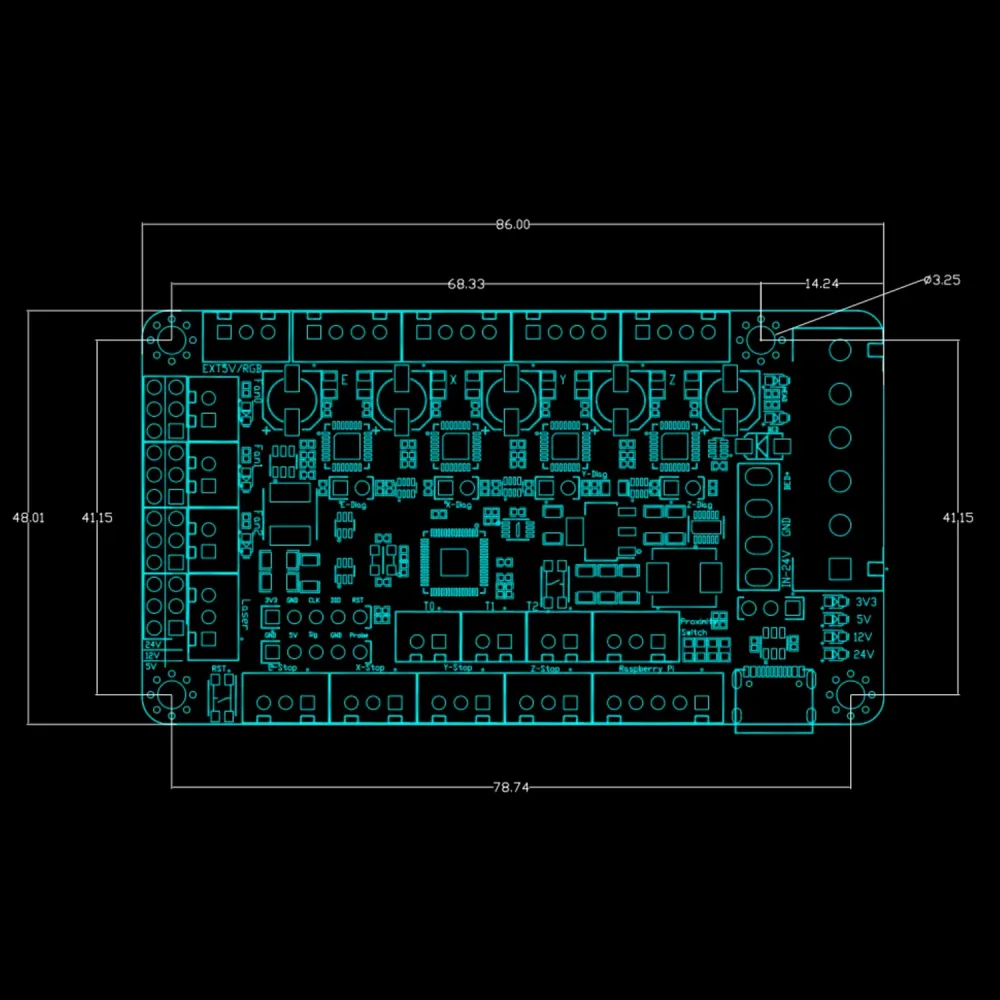
| Dimensions | 86.00 × 48.01 mm |
| Mounting | 78.74 × 41.15 mm hole centres; Ø3.25 mm holes |
| Contents | 1 FYSETC R4 V1.0 board |
The 20 A fuse protects the common power input; it is not the continuous-current rating of each output. FYSETC does not publish a separately verified continuous thermal limit for BED, HEAD or each fan output in this repository. Loads, wiring, connectors, cooling and protection must therefore be sized with suitable margin.
Voron V0 compatibility
The four-driver architecture suits a conventional Voron V0: two CoreXY motors, one Z motor and one extruder. It can be used in V0, V0.1 or V0.2/V0.2r1 projects when the electronics mount, wiring and Klipper configuration are correctly adapted.
| Application | Assessment | Checks required |
|---|---|---|
| Voron V0 / V0.1 | Intended, conditional use | Mount, connector positions, 24 V harness and configuration for the exact machine revision. |
| Voron V0.2 / V0.2r1 | Suitable as a four-motor controller | Not a universal drop-in replacement: check mounting, toolhead, endstops, probe, fans and current configuration file. |
| Custom compact printer | Possible | 24 V system, no more than four motors, Klipper, load power and all required inputs/outputs. |
| Independent dual-Z or more than four motors | Not directly supported | Only four drivers are provided, and the integrated devices cannot be replaced by plug-in modules. |
A shared Voron V0 name does not prove that two revisions use identical mounts, connectors or assignments. Start from the manual and a current Klipper configuration for the exact printer revision, then use this board's pin table to adapt the R4.
Complete Klipper pinout
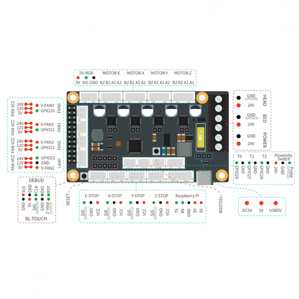
The following table summarises R4 V1.0 signals. Direction and enable inversion marks must be selected according to the actual motor direction and peripheral logic; the GPIO number alone does not determine those marks.
| Function | GPIO / value | Notes |
|---|---|---|
| X motor | STEP gpio3 · DIR gpio2 · EN gpio4 | TMC2209 UART address 1 |
| Y motor | STEP gpio16 · DIR gpio15 · EN gpio14 | TMC2209 UART address 2 |
| Z motor | STEP gpio19 · DIR gpio18 · EN gpio17 | TMC2209 UART address 3 |
| E extruder | STEP gpio6 · DIR gpio5 · EN gpio7 | TMC2209 UART address 0 |
| TMC2209 UART | RX gpio9 · TX gpio8 | Shared bus; 0.220 Ω sense resistors |
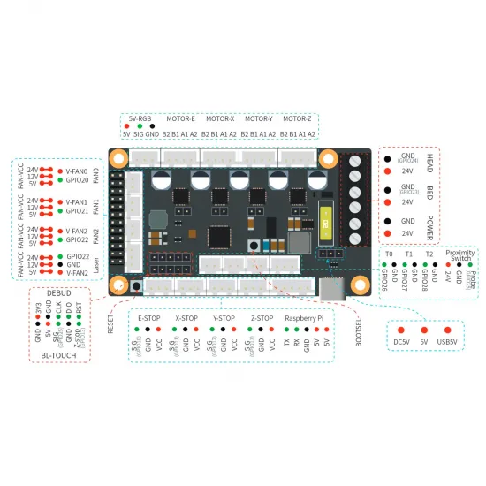
| E / X / Y / Z STOP | gpio10 / gpio11 / gpio12 / gpio13 | Selectable sensor supply; check jumpers |
| T0 / T1 / T2 | gpio26 / gpio27 / gpio28 | ADC inputs; assign to hotend, bed or chamber according to wiring |
| HEAD / BED | gpio24 / gpio23 | 24 V power outputs with common positive |
| FAN0 / FAN1 / FAN2 | gpio20 / gpio21 / gpio22 | Select 5, 12 or 24 V before connection |
| PROBE | gpio25 | Probe input; verify connector and voltage |
| BLTouch | Sensor gpio25 · control gpio13 | gpio13 is shared with Z-STOP |
| Addressable RGB | gpio29 | 5 V, signal and GND connector |
| Host UART | TX gpio0 · RX gpio1 | Available in addition to USB; verify host power separately |
Integrated TMC2209 drivers and current setting
The TMC2209 drivers provide UART control, MicroPlyer interpolation, StealthChop2, SpreadCycle and StallGuard4 diagnostics. They are soldered to this board, not removable modules, and their practical capacity depends on PCB and electronics-bay cooling.
In Klipper, all four drivers share the UART pins and are selected by address:
[tmc2209 stepper_x]
uart_pin: gpio9
tx_pin: gpio8
uart_address: 1
sense_resistor: 0.220
# run_current: set for the actual motor and cooling

# Remaining addresses: extruder 0, Y 2, Z 3
run_current is an RMS current and must be calculated for the installed motor with thermal margin. Do not copy current values from another build. Current Klipper documentation generally advises against reducing current through hold_current; use it only when its effects are understood.
Endstops, DIAG and probes
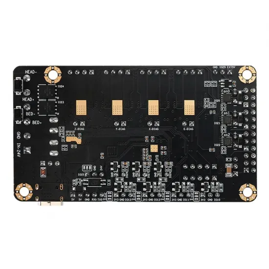
Each TMC2209 has a DIAG jumper that can route its diagnostic output to the corresponding endstop input for sensorless homing. When a conventional microswitch is used, keep the DIAG jumper in the appropriate state to avoid driving the input from two sources.
The E/X/Y/Z-STOP connectors offer selectable 3.3 or 24 V sensor power. A typical mechanical endstop does not require 24 V: connect only the contacts required by the schematic and check the logic with QUERY_ENDSTOPS before moving the machine.
The board also provides a proximity input and BLTouch header. For BLTouch, gpio13 shares the Z-STOP function and gpio25 is the probe signal. Follow the pinout image, verify connector orientation and never infer a wire's function solely from its colour. A passive probe such as the FYSETC PCB Klicky Probe can use a suitable input when its wiring, mount and configuration are respected; it is not a universal plug-and-play accessory.
Thermistors: T0, T1 and T2
The physical T0, T1 and T2 connectors map to gpio26, gpio27 and gpio28. They are not permanently tied to a specific machine function. FYSETC's example, for instance, uses gpio28 for the hotend, gpio26 for the bed and gpio27 for the chamber.
Each Klipper section must match the physical pin, actual sensor model and safe limits. With a cold machine, every reading must be physically plausible and close to ambient temperature before enabling a heater. An impossible, fixed or inverted reading must be resolved first.
Fans and voltage selection
FAN0, FAN1 and FAN2 can each be physically selected for 5, 12 or 24 V with jumpers. Firmware does not make this voltage selection.
- Disconnect both the power supply and USB.
- Check the nominal voltage printed on each fan.
- Place that output's jumper on 5 V, 12 V or 24 V.
- Verify polarity and connector orientation before applying power.
- Test each output at low speed and confirm stable rotation.
The output marked Laser shares gpio22 with FAN2 and is not an additional channel. Do not use both functions simultaneously. Any laser application requires suitable enclosure, interlocks, extraction and eye protection beyond a normal 3D-printer installation.
Compiling Klipper for FYSETC R4
From a current Klipper installation:
cd ~/klipper
make menuconfig
Select the options documented by FYSETC:
Enable extra low-level configuration options: enabled.Micro-controller Architecture:Raspberry Pi RP2040.Communication interface:USB.
Save and compile:
make clean
make
Loading the UF2 firmware
- Connect the board over USB-C while following the intended power procedure for the installation.
- Hold
BOOTSEL. - Press and release
RESET, then releaseBOOTSEL. - The host should detect a drive named
RPI-RP2. - Copy
~/klipper/out/klipper.uf2to that drive. - After restart, find the persistent port with
ls /dev/serial/by-id/.
[mcu]
serial: /dev/serial/by-id/usb-Klipper_rp2040_YOUR-BOARD-IDENTIFIER-if00
restart_method: command
Do not copy another user's USB identifier: each board has its own. If it does not appear, check the USB cable —many are charge-only—, BOOTSEL mode, the compiled firmware and host logs.
Using FYSETC's example configuration
The official printer.cfg is useful as a pin reference, but it should not be installed wholesale without an audit. It contains the original user's USB identifier and example values for travel, homing, motors, extruder, thermistors, PID, speeds and temperatures.
Start from a current configuration for your exact Voron V0 revision and adapt only the sections needed for the R4. Check in particular:
- kinematics, motor directions, microsteps and
rotation_distance; - extruder ratio and effective drive-gear diameter;
- RMS current for each motor and driver cooling;
- position and logic of each endstop or DIAG input;
- type and pin of every temperature sensor;
- travel limits and homing coordinates;
- maximum heater and fan power;
- PID and thermal protection on the assembled machine.
Safe commissioning sequence
- Complete all wiring with both 24 V and USB disconnected.
- Confirm the
R4_V1silkscreen and compare every connector with the pinout. - Set fan and sensor voltage selectors before connecting peripherals.
- Verify continuity, polarity, terminal tightness, wire cross-section and fuse.
- First power up without high-power loads and establish MCU communication.
- Validate endstops with
QUERY_ENDSTOPSwithout moving the axes. - Confirm that all temperature channels report physically plausible values.
- Test motors one at a time at low speed; correct direction in configuration and never swap wires while powered.
- Test fans and heaters individually while monitoring voltage, current and connector temperature.
- Complete motion, extrusion, PID and limit calibration before unattended printing.
Dimensions and mounting
The board measures 86.00 × 48.01 mm. Its four mounting centres form a 78.74 × 41.15 mm rectangle and the holes are Ø3.25 mm. Allow additional clearance for USB-C, the power terminal, fuse, side connectors and airflow across the TMC2209 drivers.
Official documentation
The official FYSETC R4 repository provides the schematic, CAD, pinout, compile options, UF2 procedure and Klipper example file. Always confirm that the documents match the silkscreen on your own board.