

- Stock: 4
- Model: Spider3-Fysetc-X-Voron

Version:

3
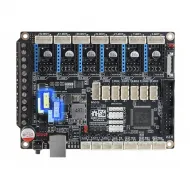
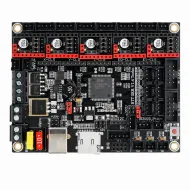
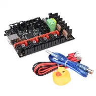
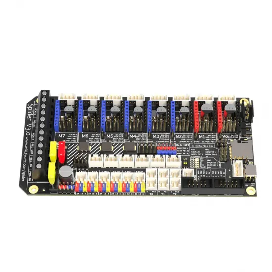
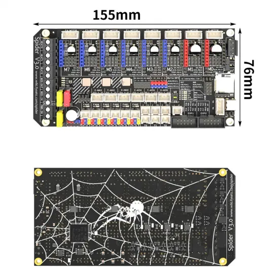
The FYSETC Spider V3.0 F446 is a 32-bit control board designed for 3D printers with many motors and peripherals. It combines a 180 MHz STM32F446, eight replaceable driver sockets, three hotend outputs, one bed output, six fan connectors and an onboard CAN transceiver in a compact 155.3 × 76.5 mm format.
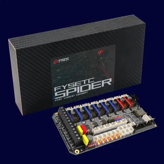
Its layout is particularly suitable for Voron 2.4 R2 and Voron Trident projects, for which FYSETC publishes dedicated wiring diagrams. It can also be integrated into other CoreXY and custom machines when mounting, wiring and firmware are properly adapted.
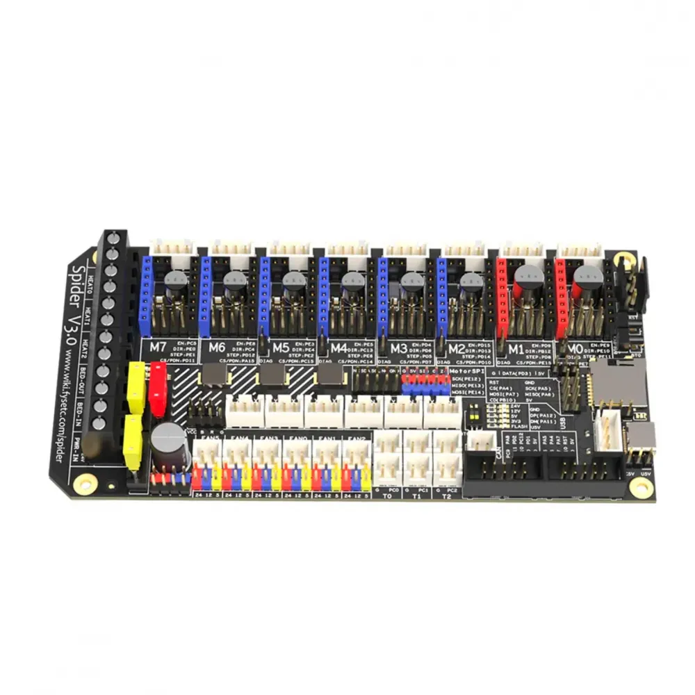
Main specifications
| Item | Specification |
|---|---|
| MCU | STM32F446, 180 MHz |
| Drivers | 8 replaceable M0-M7 sockets; STEP/DIR and, depending on module, UART or SPI |
| Main power | Nominal 24 V DC, with a separate bed input |
| HV drivers | Separate input for M0 and M1; board path marked up to 60 V, always limited by the installed driver |
| Heating | 1 bed and 3 HE0-HE2 heater outputs |
| Temperature | 6 inputs with 4.7 kΩ pull-ups for NTC or PT1000; PT100 through an external amplifier |
| Fans | 6 FAN0-FAN5 outputs selectable for 5, 12 or 24 V by jumper |
| Communications | USB-C, CAN, UART, SPI, I2C, EXP1/EXP2 and NeoPixel |
| Storage | Onboard microSD, external SD header and 4 KiB I2C EEPROM |
| Dimensions | 155.3 × 76.5 mm |
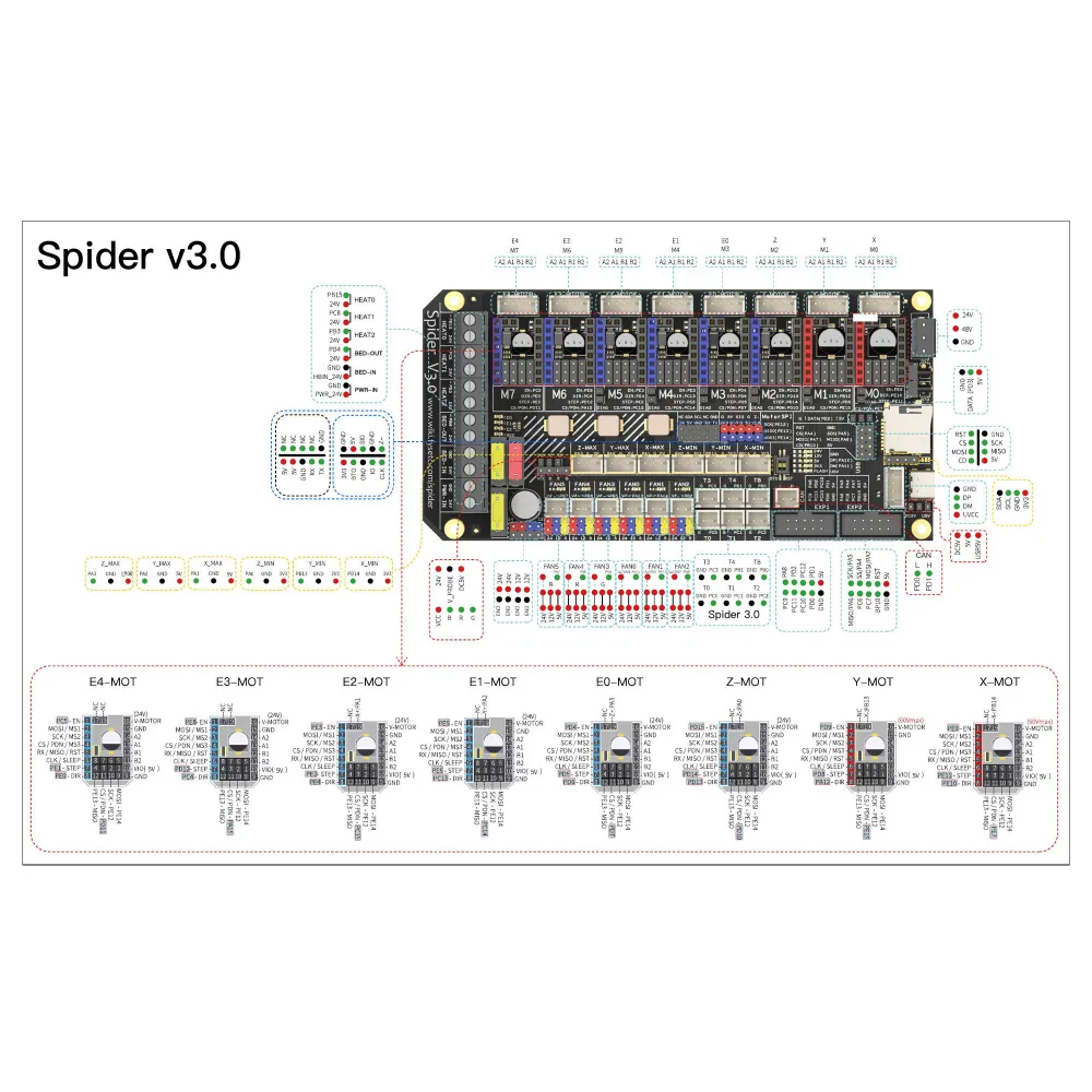
Eight replaceable drivers
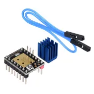
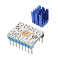
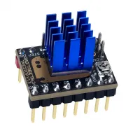
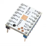
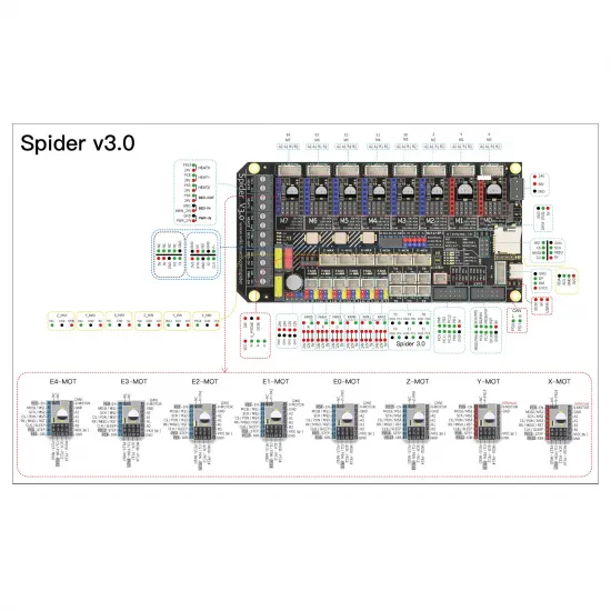
The eight M0-M7 sockets let you select the appropriate driver for each axis or extruder. The board supports STEP/DIR control and provides UART and SPI connections, but effective compatibility depends on the specific module's format, pinout, voltage, current, communication mode and cooling.
It may be combined, for example, with the BIGTREETECH TMC2209 V1.3 in UART mode or the FYSETC TMC2130 V1.2 in SPI mode, with jumpers and firmware configured for each model. DIAG inputs share signals with endstops, so sensorless homing requires compatible drivers and deliberate configuration; they are not simultaneous independent inputs.
Main power and outputs
Spider V3.0 uses a nominal 24 V main input and a separate heated-bed input. The official schematic includes 20 A fuses on both inputs and 10 A protection on the VMOT branch. These figures describe circuit protection: they do not replace load calculations or guarantee that current continuously through connectors, traces or loads.
The board generates auxiliary 12 V, system 5 V and Raspberry Pi 5 V rails, each protected at 3 A in the V3.0 schematic. Combined loading on each rail must remain within its limits with suitable ventilation. Bed and HE0-HE2 outputs require wiring, terminals and connectors sized for the actual load.
Separate HV input for M0 and M1
The two red M0 and M1 sockets can use the regular 24 V supply or a separate motor supply. FYSETC marks this board path for up to 60 V, but the safe voltage is always the lowest rating among the board, driver, StepStick module, its capacitors and the rest of the circuit.
When using the regular 24 V supply, the bridge shown in the pinout must be fitted. With an external HV supply, this bridge must be removed or configured according to the diagram and the higher voltage must remain limited to M0/M1. A TMC2209 must not be used at 48 V. The BIGTREETECH TMC2240, for example, is limited to 36 V, so that lower limit applies and reasonable margin should be left.
5, 12 or 24 V fans
FAN0-FAN5 are controllable outputs whose voltage is selected by jumper. Before connecting each fan, check both its rated voltage and the relevant jumper position. Selecting voltage on the board neither configures the firmware pin nor protects a fan connected to the wrong voltage.
On Spider V3.0, the first three fan outputs use PA13, PA14 and PB2. Some older generic files retain assignments from previous revisions, so the photographed and archived V3.0 pinout must take precedence.
Temperature sensors, probe and endstops
Six T0-T4 and TB temperature inputs feature 4.7 kΩ pull-up resistors. Correctly configured NTC thermistors or PT1000 sensors can be used. A PT100 requires a compatible external amplifier; sharing the same diameter or cartridge format with another sensor does not imply electrical compatibility.
The six endstop connectors share signals with driver DIAG functions. A probe input is also provided. BLTouch, inductive-probe or other sensor compatibility depends on output type, voltage, pinout, logic and configuration; never connect a probe based only on wire colour.
Onboard CAN and toolboards
V3.0 includes a CAN transceiver and JST-XH connector. Its 120 Ω termination is permanently fitted, so Spider must sit at one physical end of the bus and the remote device must provide the second termination. Do not add a third terminator next to the board.
Conditional integration is possible with toolboards such as BIGTREETECH EBB36 GEN2 or BIGTREETECH EBB42 GEN2. Verify power, CAN-H/CAN-L, ground, polarity, bitrate, termination and firmware at both ends. CAN uses PD0/PD1, which are shared with EXP2 functions, so some displays may conflict.
Klipper configuration
For current Spider V3.0 F446 stock, compilation normally starts with:
Micro-controller Architecture: STMicroelectronics STM32
Processor model: STM32F446
Bootloader offset: 32 KiB
Clock Reference: 12 MHz crystal
Communication interface: USB on PA11/PA12
For a microSD update, rename the generated binary to firmware.bin. The 32 KiB bootloader places firmware at 0x08008000. A no-bootloader build uses 0x08000000 and is a different procedure that must not be mixed with the previous one.
The official generic-fysetc-spider.cfg is a pin reference, not a complete Spider V3.0 or Voron configuration. It retains some older assignments: fans, bed sensor input, drivers, currents, thermistors, directions, homing, limits, PID and geometry must be checked against the V3.0 pinout and adapted to the actual machine.
If CAN is selected as the MCU communication interface, PD0/PD1 are used and the complete bus must be configured accordingly. USB, UART and CAN are communication alternatives requiring a build consistent with the selected connection.
Marlin configuration
In current Marlin releases, the built-in definition that most closely matches the physical Spider V3.0 F446 map is:
#define MOTHERBOARD BOARD_FYSETC_SPIDER_V2_2
default_envs = STM32F446VE_fysetc_32k_bootloader
FYSETC groups Spider V2.x and V3.x pin assignments, and this definition matches the V3.0 fan and temperature layout. It must still be treated as a compilation starting point: check each output against the V3.0 pinout and configure drivers, currents, sensors, thermal protection, probe, display, kinematics and travel for the particular printer.
Do not select the 64 KiB environment or historical build names simply because they appear in an old tutorial. Firmware, bootloader and physical revision must match.
What about RepRapFirmware?
FYSETC retains a RepRapFirmware port but documents that the STM32F446's 512 KiB capacity requires some features to be removed or disabled. This is an advanced, constrained option rather than the natural path for this board; Klipper and Marlin provide more direct, maintained integration.
Voron 2.4 R2 compatibility
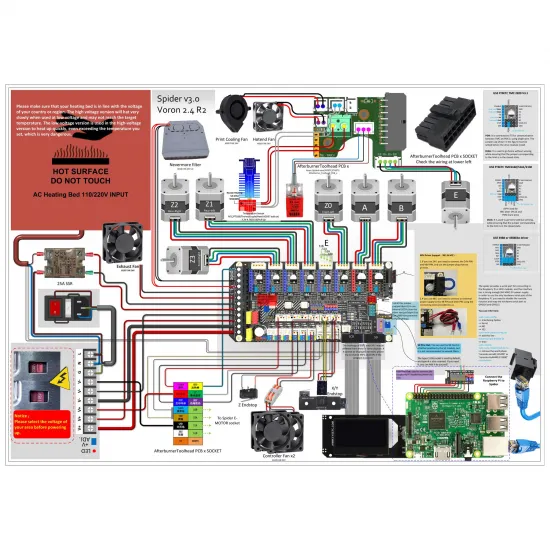
FYSETC publishes a dedicated Voron 2.4 R2 diagram. The board offers enough channels for its four independent Z motors and the remaining axes/extruder, but the diagram does not replace checking machine revision, toolhead, probe, drivers, fans, heaters, SSR, power supply and configuration.
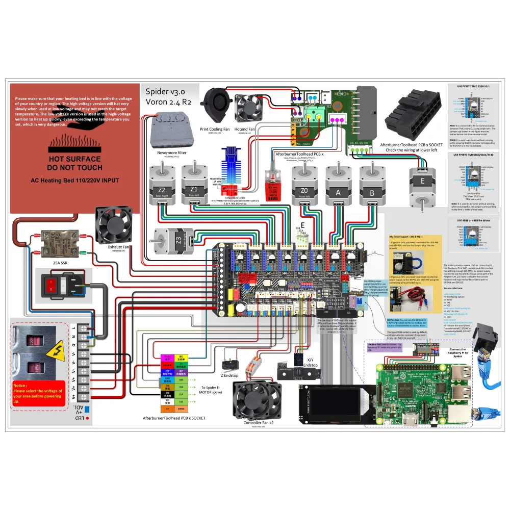
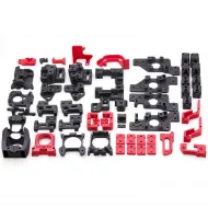
For this machine, you can also view the ABS printed parts for Voron 2.4 R2, always checking the revision and scope of each kit.
Voron Trident compatibility
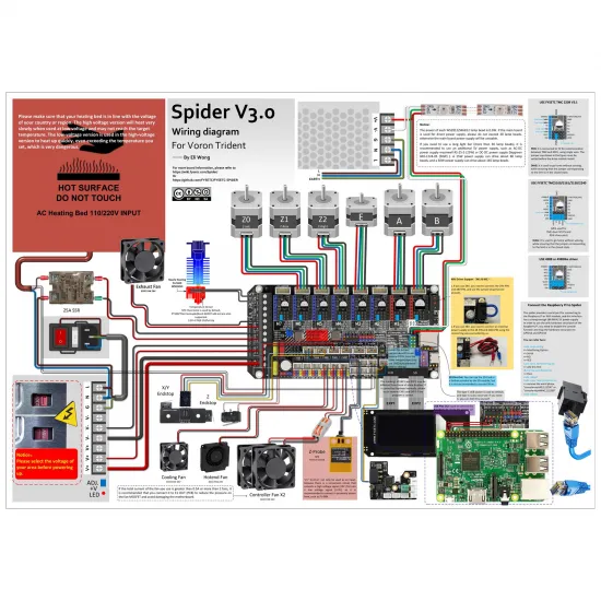
An official Voron Trident diagram is also available. Compatibility is functional and conditional: a reference diagram does not make connectors, cable lengths, probe or firmware plug and play.
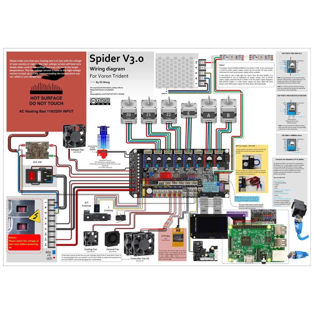
The ABS printed parts for Voron Trident may help complete the project, but must match the selected mechanical revision.
Displays and Raspberry Pi
EXP1/EXP2 support compatible displays such as the FYSETC Mini12864 V2.1, provided revision, pinout, cable orientation and firmware match. When CAN is used, remember the PD0/PD1 overlap with EXP2. On certain Mini12864 revisions, the manufacturer's R4/KILL signal warning must also be checked before pressing the encoder.
The Raspberry Pi UART header provides PA9/PA10 and a 5 V rail. Before powering the computer from the board, calculate its load together with all other 5 V devices and avoid simultaneous supplies that could backfeed each other.
This is for you if
- You need eight replaceable drivers for a Voron or multi-axis machine.
- You want to run Klipper or compile Marlin for a custom configuration.
- You need onboard CAN and understand how to place the two bus terminators.
- You want a separate supply for two higher-voltage drivers while respecting their limits.
- You will carefully check pinout, jumpers, wiring and firmware before applying power.
This is not for you if
- You need a plug-and-play board for a specific commercial printer.
- You expect preconfigured firmware without identifying sensors, drivers and machine revision.
- You intend to run any driver at 48 or 60 V without checking its individual rating.
- You require complete RepRapFirmware functionality without the documented STM32F446 memory constraints.
- You cannot verify fan, probe and peripheral voltages before connecting them.
Recommended commissioning
- Confirm that the silkscreen reads Spider V3.0 and the MCU is STM32F446.
- With every supply disconnected, configure mode, power source and jumpers for each driver and fan.
- Check polarity, continuity, earth, fuses, terminals and wire gauge.
- Compile firmware for the correct revision and bootloader.
- Power logic first and check temperatures, endstops and probe without enabling heaters.
- Test motors with conservative current and verify each fan.
- Enable bed and hotends one at a time under supervision with thermal-runaway protection active.
Contents
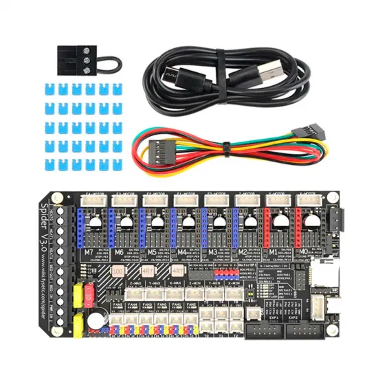
- 1 × FYSETC Spider V3.0 F446 board.
- USB cable.
- Auxiliary cable and configuration jumpers/accessories shown in the gallery.
Technical documentation: official FYSETC Spider repository, official FYSETC wiki, official Klipper generic configuration and current Marlin board list.