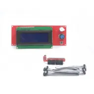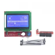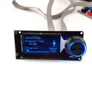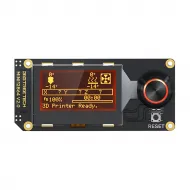


- Stock: 19
- Model: Mini12864-MKS

Model:

2004 LCD

12864 LCD

Mini 12864 LCD - Fysetc

Mini 12864 LCD - BTT

Mini 12864 LCD - MKS
Model:
Mini 12864

PI_TS35

PS50
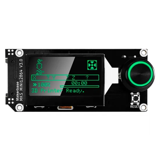
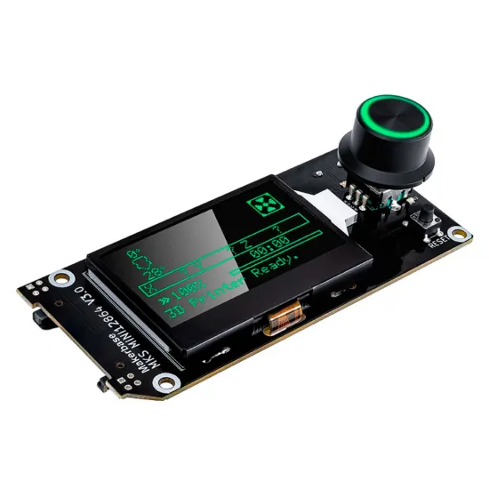
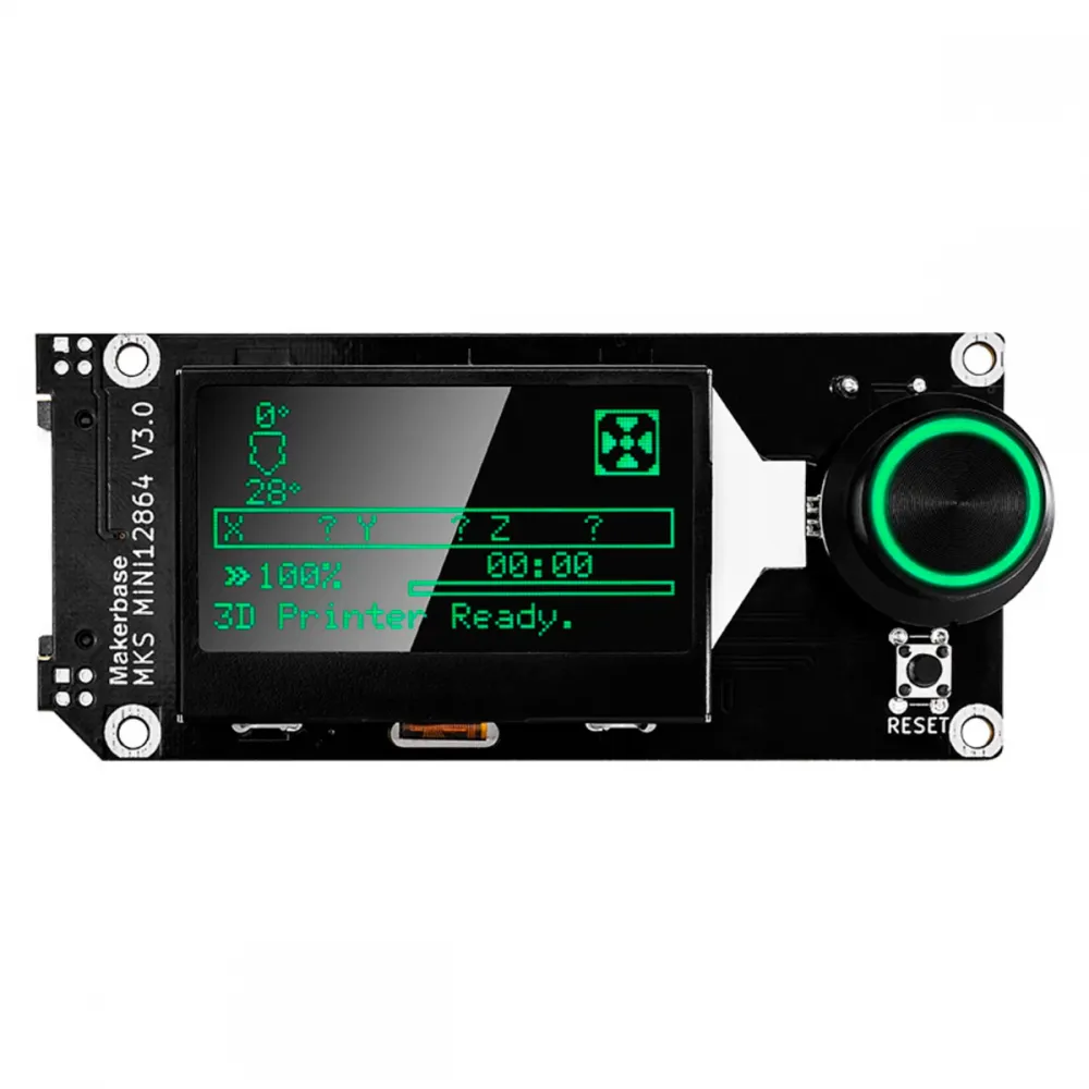
The MKS MINI12864 V3.0 is a compact 128 × 64 graphic display for 3D printers, CNC machines and electronic projects fitted with a compatible controller board. It combines a clickable rotary encoder, reset button, beeper, microSD reader and addressable RGB backlight, providing local machine control without continuously relying on a computer.
This version uses the ST7567 display controller, SPI communication and three WS2811-controlled RGB LEDs. It supports 3.3 and 5 V logic signals, but actual compatibility depends on the EXP1/EXP2 pinout and firmware configuration. The photographed unit matches the updated MKS V3.0 layout with the additional interface introduced in hardware revision V3.0_002.
Main features
- 128 × 64 graphic LCD: displays menus, temperatures, position, progress and firmware-defined machine status.
- ST7567 controller: the controller used by MKS MINI12864 V3, unlike the ST7565R fitted to earlier revisions.
- Clickable rotary encoder: direct menu navigation and selection.
- RGB backlight: three addressable LEDs driven by a WS2811 and configurable from Marlin or Klipper.
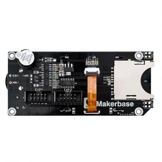
- Integrated microSD reader: functional availability depends on the board, firmware and SPI wiring.
- Reset button and beeper: integrated controls for a complete machine interface.
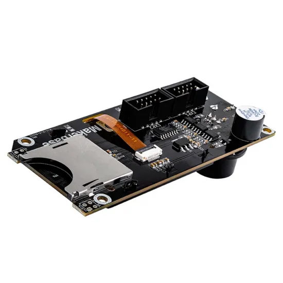
- EXP1 and EXP2: connection through two 10-pin IDC headers, subject to the controller-board pinout.
Technical specifications
| Feature | Value |
|---|---|
| Manufacturer and model | Makerbase MKS MINI12864 V3.0 |
| Resolution | 128 × 64 pixels |
| LCD controller | ST7567 |
| Communication | SPI through EXP1/EXP2 |
| Logic level | 3.3 and 5 V logic-signal compatible |
| Lighting | 3 addressable RGB LEDs, WS2811 driver and RGB order |
| Controls | Clickable encoder, reset and beeper |
| Storage | Side-access microSD slot on the pictured variant |
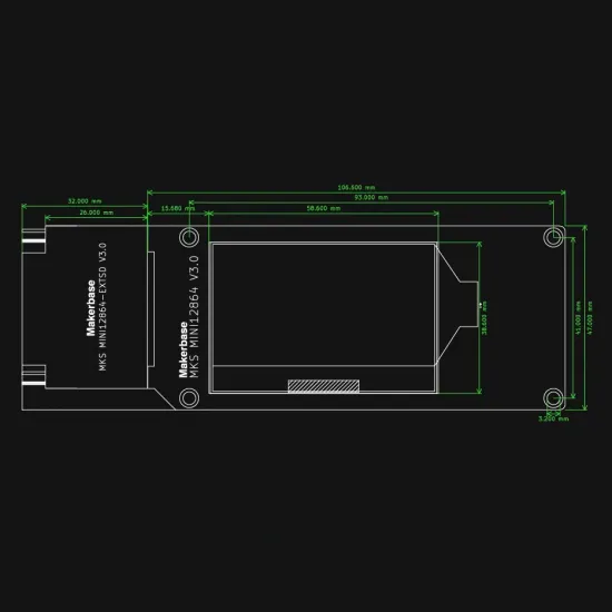
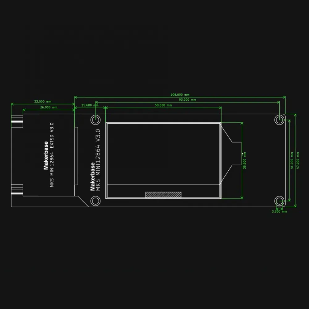
| Overall dimensions | 106.6 × 47 mm |
| Mounting centres | 93 × 44 mm |
| Mounting holes | 4 holes, Ø3.2 mm |
| Documented firmware | Marlin 2.x and Klipper; other firmware depends on the board |
Controller-board compatibility
Makerbase documents this display for MKS Robin Nano V2 and V3, MKS SGen L V1 and V2, and MKS Gen L. It is also supported by the MKS Eagle controller board available in our catalogue.
Other boards with EXP1 and EXP2 connectors may be suitable, but matching connectors do not guarantee a compatible electrical pinout. Check the exact board revision, signal assignment, voltages and firmware support before purchasing or connecting the display. This is particularly important with BIGTREETECH, FYSETC, Creality, RAMPS and other controller families that may use different orientations or assignments.
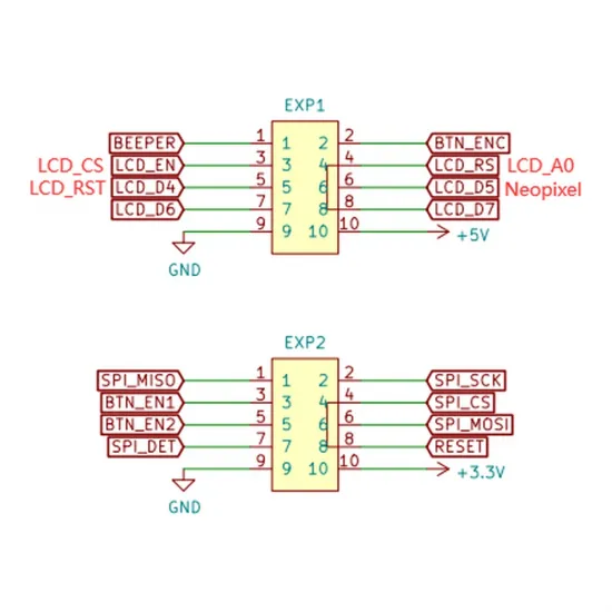
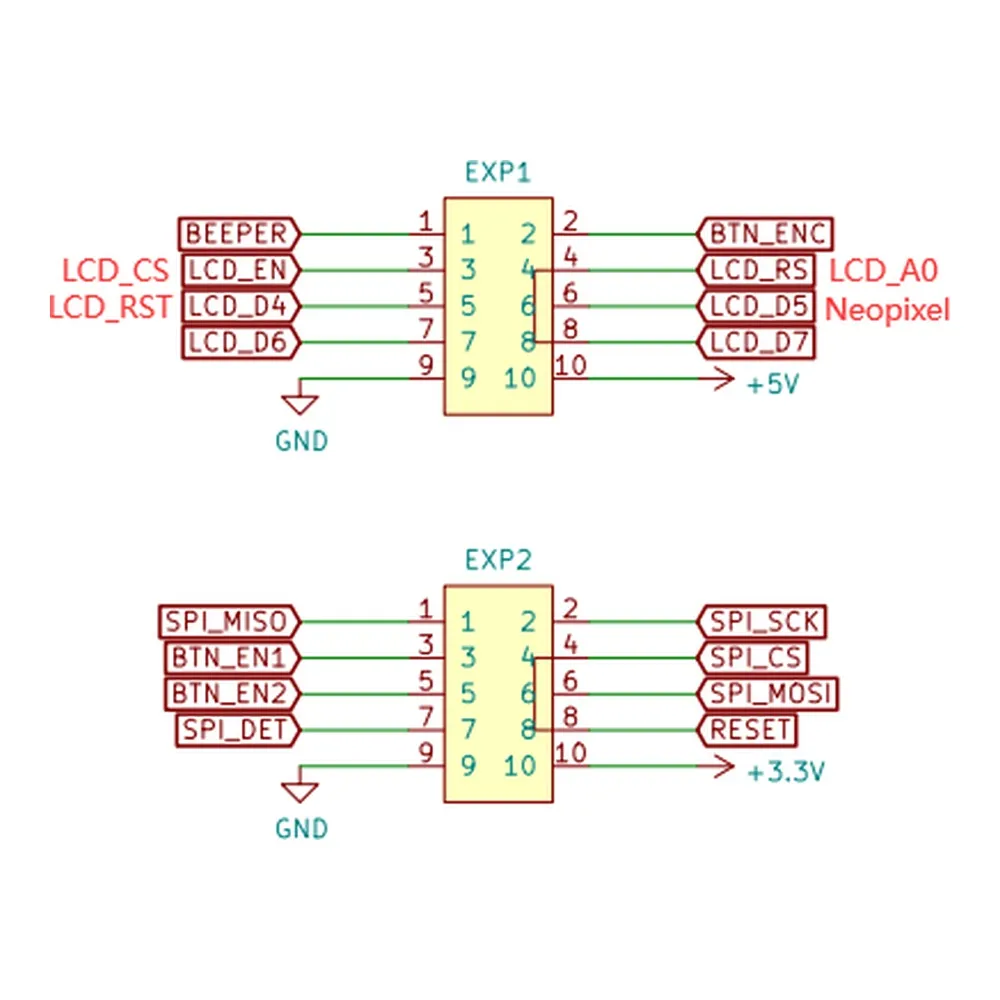
EXP1 and EXP2 pinout
| Pin | EXP1 | EXP2 |
|---|---|---|
| 1 | BEEPER | SPI_MISO |
| 2 | BTN_ENC | SPI_SCK |
| 3 | LCD_EN / LCD_CS | BTN_EN1 |
| 4 | LCD_RS / LCD_A0 | SPI_CS |
| 5 | LCD_D4 / LCD_RST | BTN_EN2 |
| 6 | LCD_D5 / NeoPixel | SPI_MOSI |
| 7 | LCD_D6 | SPI_DET |
| 8 | LCD_D7 | RESET |
| 9 | GND | GND |
| 10 | +5 V | +3.3 V |
Marlin 2.x configuration
Makerbase specifies the following options in Configuration.h:
#define MKS_MINI_12864_V3
#define NEOPIXEL_LED
Marlin must be built for the exact controller-board model and revision. Its pin definition must support the EXP1/EXP2 connections, and the NeoPixel colour order must match the RGB hardware. If colours are swapped, review the NEOPIXEL_TYPE option for your Marlin version instead of changing the wiring.
When lighting menus are enabled, the backlight can be adjusted from the display. Makerbase also documents commands such as:
M150 R255 G0 U0   ; red
M150 R0 G255 U0   ; green
M150 R0 G0 U255   ; blue
Available options and colour persistence may vary between Marlin versions. After compiling, test the LCD, encoder, click, beeper, RGB LEDs and microSD separately.
Klipper configuration
Makerbase publishes the following reference block. The EXP1_n and EXP2_n aliases must be defined for the controller board in use:
[display]
lcd_type: uc1701
cs_pin: EXP1_3
a0_pin: EXP1_4
rst_pin: EXP1_5
contrast: 63
encoder_pins: ^EXP2_5, ^EXP2_3
click_pin: ^!EXP1_2
spi_software_miso_pin: EXP2_1
spi_software_mosi_pin: EXP2_6
spi_software_sclk_pin: EXP2_2

[output_pin beeper]
pin: EXP1_1

[neopixel mks_mini12864]
pin: EXP1_6
chain_count: 3
color_order: RGB
initial_RED: 1.0
initial_GREEN: 1.0
initial_BLUE: 1.0
This block is not universal by itself. It must be combined with the [board_pins] section for the exact board. Some controllers require a hardware SPI bus through spi_bus, while others use the software SPI pins shown above. Do not enable both alternatives without checking the board configuration.
The configuration may be stored separately and loaded from printer.cfg with:
[include mks_mini_12864_v3.cfg]RepRapFirmware use
Makerbase does not publish a dedicated RepRapFirmware configuration for this display. Some Duet or compatible boards support directly connected 12864 graphic displays, but compatibility depends on the controller model, LCD expansion hardware, pinout and firmware version.
It should not be treated as a universal RepRapFirmware display. The controller documentation must explicitly confirm support for a compatible ST7567/UC1701-type LCD and matching electrical assignment. Even when the LCD and encoder work, the microSD reader, beeper or RGB lighting may require additional configuration or remain unsupported.
Safe installation and testing
- Disconnect both the machine power supply and USB cable.
- Consult the schematic for the exact controller-board revision.
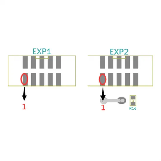
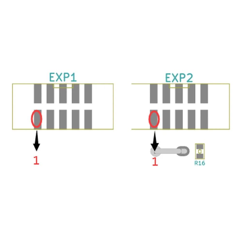
- Locate pin 1, GND, +5 V and +3.3 V at both ends before fitting the cables.
- Verify that EXP1 and EXP2 follow the actual pinout rather than relying only on connector keying.
- Configure and compile the firmware before the first test when required.
- Power up and test the image and encoder first, followed by the beeper, RGB LEDs and microSD.
- If the display remains blank or behaves abnormally, switch off and recheck the wiring. Do not try random cable orientations.
Differences from MKS MINI12864 V1 and V2
V3 uses an ST7567 instead of the ST7565R found on earlier versions, adds addressable RGB lighting and normally displays light text on a dark background. A configuration intended for MKS MINI12864 V1/V2 should therefore not be copied without review: the physical format is similar, but the controller and lighting arrangement differ.
The MKS MINI12864 V3.0 is particularly useful for custom machines requiring a compact, complete and configurable local interface. Installation can be straightforward on officially supported MKS boards, but any other controller should be treated as a hardware integration: verify the pinout first and configure the firmware second.
```