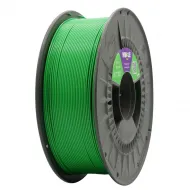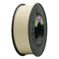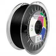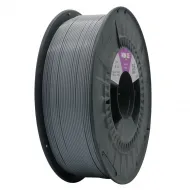
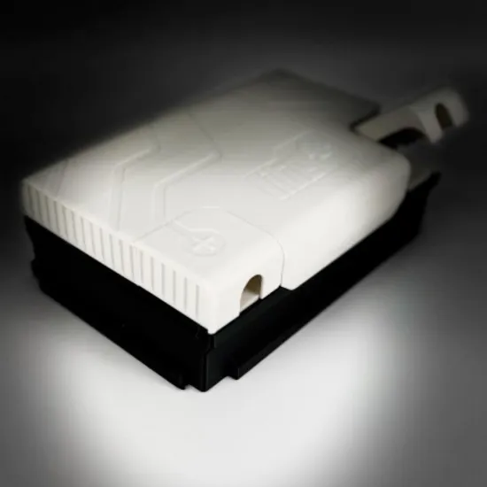
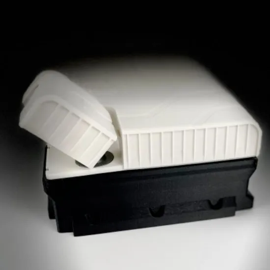


- Stock: 1
- Model: PETG-V0-SAKATA3D-1.75mm

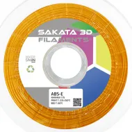
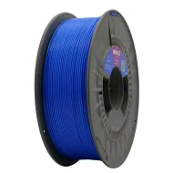
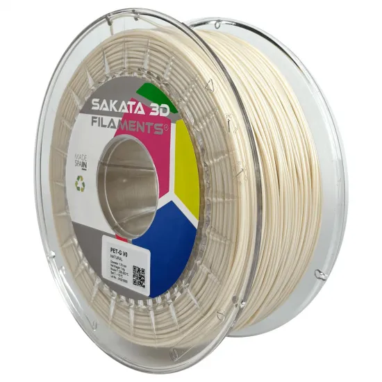
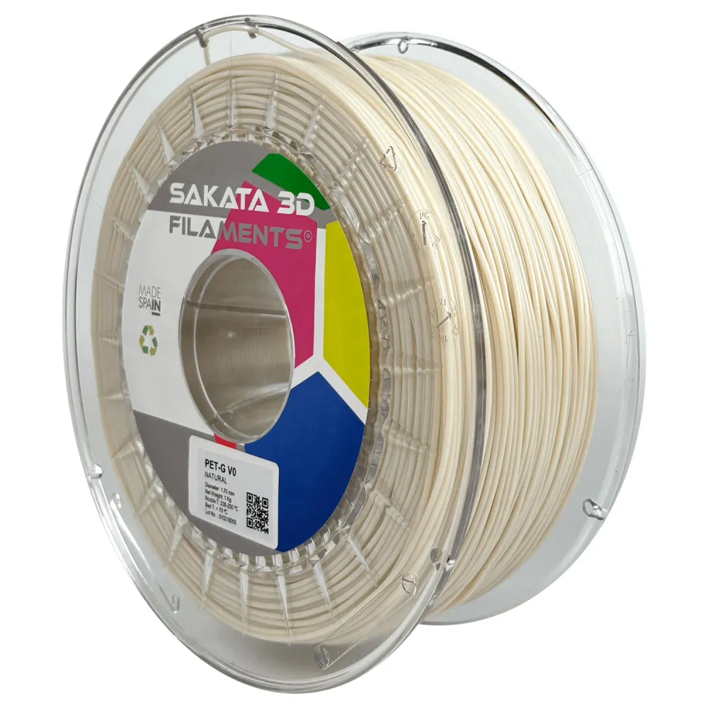
Sakata 3D PET-G V0 Natural filament in 1.75 mm and 1 kg, made in Spain for printed parts requiring improved flame behaviour compared with conventional PET-G. Sakata 3D declares a UL 94 V-0 rating on 1.5 and 3.0 mm 3D-printed specimens, together with a formulation free from halogenated flame retardants, red phosphorus and PFAS substances.
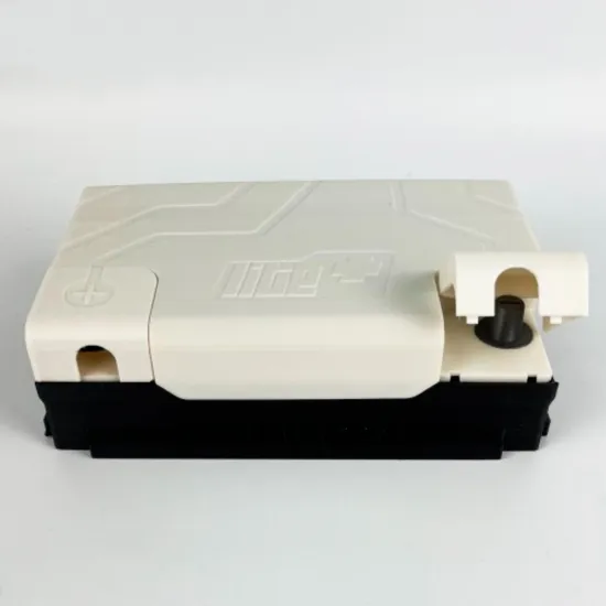
It is particularly relevant for technical prototypes, housings, brackets and components near electronics where reduced flame propagation is desirable. It must not be confused with a non-combustible material: geometry, thickness, orientation, print settings and final use all affect the behaviour of a finished part.
Format and characteristics
| Property | Value |
|---|---|
| Material | Flame-retardant PET-G V0 |
| Colour | Natural |
| Diameter | 1.75 ± 0.03 mm |
| Maximum roundness deviation | 0.03 mm |
| Net weight | 1,000 g |
| Density | 1.26 g/cm³, ISO 1183 |
| Theoretical length | Approximately 330 m, calculated from weight, diameter and density |
| Specified nozzle | Brass; the TDS does not require a hardened nozzle for abrasion |
| Origin | Made in Spain by Polimersia Global S.L. |
What UL 94 V-0 means
UL 94 V-0 describes the behaviour of a vertical specimen exposed to a small, controlled flame. Its criteria include each period of flaming combustion ending within 10 seconds, combustion not reaching the upper clamp and no flaming particles falling and igniting the cotton indicator below.
Sakata 3D's technical data sheet declares V-0 at thicknesses of 1.5 and 3.0 mm on 3D-printed bars measuring 125 (±5) × 13.0 (±0.5) mm. This is more relevant than assigning the rating only to the raw resin, but it still applies to specific specimens and test conditions.
The filament is not certified by Underwriters Laboratories and has no UL number. A printed part is therefore not automatically certified, approved or accepted for an electrical or fire-safety application. Where compliance is mandatory, the final product must be tested or certified using its actual geometry, thickness, colour, orientation, settings and production batch.
Declared flammability data
| Test | Result | Specimen type |
|---|---|---|
| UL 94, 1.5 mm | V-0 | 3D-printed bar |
| UL 94, 3.0 mm | V-0 | 3D-printed bar |
| Oxygen index, ASTM D2863 | 35% | Injection-moulded bar |
| GWFI, IEC 60695-2-12 | 960°C at 1 and 2 mm | Injection-moulded bar |
| GWIT, IEC 60695-2-13 | 775°C at 1 and 2 mm | Injection-moulded bar |
| Comparative tracking index | 600 V, solution A | Injection-moulded bar |
Tests performed on injection-moulded bars characterise the reference material but do not guarantee that an FFF part will reproduce the same result. They also do not replace insulation distances, protective devices, thermal limits or any requirements applying to the finished equipment.
Reference mechanical and thermal properties
| Property | Official value |
|---|---|
| Tensile modulus, ISO 527 | 2,350 MPa |
| Tensile strength at yield, ISO 527 | 40 MPa |
| Elongation at break, ISO 527 | 40% |
| Notched Charpy impact, ISO 179 | 3 kJ/m² |
| Unnotched Charpy impact, ISO 179 | No break |
| HDT at 0.45 MPa, ISO 75 | 63°C |
| HDT at 1.8 MPa, ISO 75 | 58°C |
| Vicat softening temperature, ISO 306 | 70°C |
These values were obtained from injection-moulded bars. A printed part depends on orientation, wall count, infill, interlayer bonding, moisture and geometry. HDT and Vicat do not by themselves define a universal continuous service temperature.
Suggested starting profile
| Setting | Reference |
|---|---|
| Nozzle | 235-250°C |
| Heated bed | Above 70°C |
| Build surface | Glass or PEI |
| Part-cooling fan | 40-90% |
| Reference layer height | 0.2 mm |
| Published speed range | 20-250 mm/s |
| Conservative starting point | 40-80 mm/s, increasing only after checking flow and layer bonding |
| Pre-drying | 4-6 hours at 60°C |
| During printing | Feeding at 60°C is optional |
250 mm/s is the upper end of the manufacturer's published range, not a guaranteed speed. To increase speed, the hotend must melt the required volumetric flow while the part retains adequate interlayer bonding. For components intended to validate flame behaviour, changes to layer height, orientation, walls, infill or temperature may affect the outcome.
Tuning, moisture and bed adhesion
- Dry the spool after exposure to ambient humidity or if popping, bubbles, excessive stringing or a rough surface appear. Confirm that both spool and dryer can withstand 60°C.
- Start within the official range using a temperature tower and flow test. Prioritise consistent layer bonding over maximum speed.
- Adjust cooling to geometry: more fan improves bridges and detail, while less fan generally favours interlayer bonding.
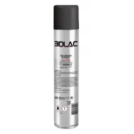
- On glass or highly adhesive surfaces, a thin layer of 3DLAC aerosol or 3DLAC Plus may be used as an adhesion aid or release layer.
- Allow the part to cool before removal and store the remaining filament sealed with desiccant.
3D printer compatibility
It can be profiled on FDM/FFF printers for 1.75 mm filament whose hotend reaches 250°C and whose bed can remain above 70°C. This includes suitable HPRO, Bambu Lab A1/P1/X1, Creality Ender-3 V3 or K1, Prusa MK3/MK4/XL and Voron configurations, provided the actual printer, surface and profile meet those requirements.
Mechanical spool compatibility with AMS, AMS Lite, MMU, CFS or other automatic material systems is not guaranteed. Check dimensions, filament path and friction; use an external spool holder when in doubt.
If V-0 behaviour is unnecessary and you prefer a wider colour range or a general-purpose material, see the standard Sakata 3D PET-G.
Applications and limitations
- Electronic housings and brackets for prototypes or short production runs.
- Conduits, spacers and auxiliary parts where reducing sustained flaming is desirable.
- Functional prototypes used to evaluate geometry before testing or certifying the finished product.
- Technical parts requiring PET-G's characteristic printability and low shrinkage.
It is not certified for food contact or medical applications. It must not be used as the only safety measure in components connected to mains power, batteries, heaters or critical equipment. The finished design must incorporate the appropriate electrical, thermal and mechanical protection and pass every test required for its application.
This is for you if
- You want a technical PET-G from a Spanish brand with declared V-0 behaviour on printed specimens.
- You need to make prototypes, brackets or housings that will subsequently be validated as a finished assembly.
- Your printer supports 1.75 mm filament, a 235-250°C nozzle and a bed above 70°C.
This is not for you if
- You require filament carrying UL certification and a UL number: this product has neither.
- You expect every printed part to be automatically approved or non-combustible.
- You require food-contact, medical or guaranteed service-temperature certification for your design.
Frequently asked questions
Is the filament UL certified?
No. Sakata 3D declares UL 94 V-0 results at 1.5 and 3.0 mm on printed specimens, but its own TDS states that the filament is not certified by Underwriters Laboratories and has no UL number.
Will a printed housing automatically be V-0?
This cannot be assumed. Thickness, orientation, walls, infill, colour, settings, batch and geometry may change the result. Where it is a mandatory requirement, test the part or finished product.
Does it require a hardened nozzle?
The TDS specifies a brass nozzle, so it is not treated as an abrasive material that requires a hardened nozzle by default.
Can it be printed at 250 mm/s?
This is the maximum of the published range, not a guarantee. Actual speed depends on hotend flow, nozzle, line height and width, acceleration, geometry and interlayer bonding.